Operative Lines Tendon Projection
Important
This function is only available for users of SOFiSTiK Analysis + Design with interface to SOFiSTiK FEA
Allows to define the projection of prestressing tendon ducts within slab elements. Corresponding to this definition, tendon elements are generated during the analysis of systems where the tendon projections are visible in the Revit view.
The following steps enable you to create a Tendon Projection:
Make sure at least one pre-stressing system is available in your project (for this, use )
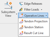
Click on
Create Tendon ProjectionThe ribbon Place Lines is started with the preset line style SOF_TendonProjection
If necessary, adjust the Placement Plane of the line to be in the plane of the slab element
Draw one or several lines
Click on a SOFiSTiK Tendon Projection line and use the SOFiSTiK Structural Properties panel to adjust the tendon’s settings
Tip
Tendon Projections are standard Revit Model Lines with a specific type. Use Revit functions to easily move, copy, adjust etc Tendon Projections in your model.
Definition of Tendon Projections
The SOFiSTiK Structural Properties panel allows you to adjust the tendon’s settings.
General
Prestressing System of choice and a specific name for the tendon (optional).
Geometry
During the tendon definition, you can choose between automatic and user defined layout. Depending on your choice, the following options are available for the tendon geometry:
Automatic tendon layouts:
Layout is defined by the overall settings for the Tendon Projection in SOFiSTiK Structural Properties, it is possible to (de-)activate individual Tendon Stations intersecting the projection. Stations are always interpreted as high points.
List of available parameters:
Parameter
Description
Distance from top
Valid for points along axis where a Tendon Station intersects(see Stations below)Distance from bottom
Valid for all points between stations
Straight length at top
Segment with curvature 0°
Transition length
Horizontal distance between top and bottom points
Stations
Sub-menu to (de-)activate which intersecting tendon stations are considered. Stations are always interpreted as high points.
Note
Start and end point are centered over the height of the slab. To change this, create a Tendon Station.
User defined layouts
Layout is defined by the individual settings for the Tendon Projection at each station in the respective sub-menu. It is possible to (de-)activate individual Tendon Stations intersecting the projection. Stations are either interpreted as high points or low points.
List of available parameters:
Parameter
Description
Stations
Sub-menu to- (de-)activate which intersecting Tendon Stations are considered- define axis reference and distance- define inclination and straight lengths to either side of the station
Construction Sequence
Define the construction stage for the prestressing application and grouting. For further information, see Tendon Manual.
Prestressing
Define other settings about the prestressing. For further information, see Tendon Manual.
Tip
Use multiselect to define settings for multiple tendons at once.
Note
When analyzing a Revit View where a tendon projection line is visible, a tendon will automatically be generated and calculated according to the settings made in Revit.


