Axis Dialog
In the Axis Dialog you can define the axis geometry, variables and create additional secondary axes. Axis definition has direct influence to the Superstructure and Substructure elements.
Changes in axis definition (using Edit Axis command) will update Component and Substructure elements.
Axis dialog is divided into following tabs: Alignment, Variables, Secondary Axes
Alignment tab
Define horizontal and vertical alignment and placements (points of interest) along the axis at the chosen stations.
Horizontal Alignment
Horizontal Alignment is defined using alignment parameters. You can choose from different types of curves and define the length, start- and end radius. Stations will be calculated automatically according to the length of each curve and Station at Start value.
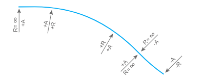
An axis is always based on a starting point (coordinates x,y) and a tangential direction. The user can define the lengths and curvatures of each section, from which the values of the tangents are then calculated. For the radii values, positive values indicate a curve to the right and negative values indicate a curve to the left.
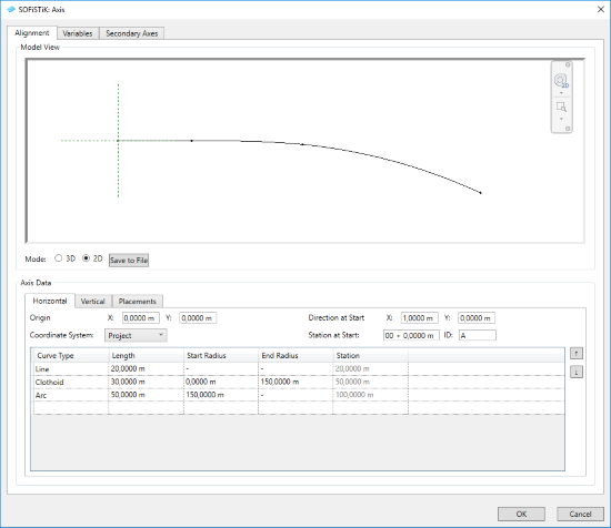
Origin - X,Y coordinates - you can define the starting point of an axis with coordinates according to the chosen coordinate system.
- Coordinate System
Project - related to the Project Base Point
Shared - related to the Survey Point
Internal - related to the Internal Origin
Derivative at Start - X,Y lengths - you can define the orientation of the axis at the starting point with X and Y values.
Station at Start - is divided into two input sections. First one is the mileage of the beginning of the axis. Second one is the value of the first station.
ID - Axis ID is used in the names of the Component and created views. It helps you also to navigate in your project.
Vertical Alignment
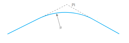
Define vertical alignment of an axis along stations using z-coordinates of the tangential intersection points and the radii of curvature along the axis at the preset station positions.
The height development is independent of the alignment in plan. The curves follow a quadratic parabolic, circular or unsymmertic curve. You can select curvature type in ‘Type’ column. Vertical Alinment is calculated according to the Base Elevation and selected coordinate system (in Horizontal Alignment tab)
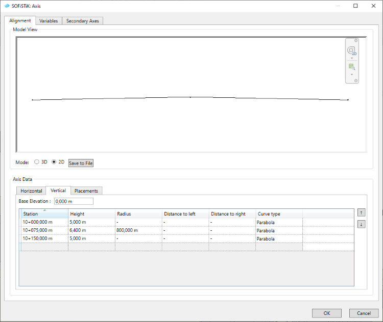
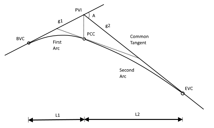
In case of unsymmetric curve use the Distance to Left and Distance to Right to determine the range (Length L1 and L2) of each curvature from Intersection Point.
Placements
Define the position and other characteristics of the Placements. Placement’s definition is important for further modeling of component and substructure elements.
For each of the Placements, a local plane is automatically created for the structural elements (substructures, etc.). The working planes are aligned perpendicular to the axis or defined always vertical (global z-direction) Additional rotations can be specified.
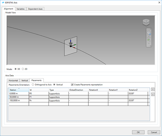
- Placement’s Orientation - defines the orientation of the placement plane.
Orthogonal to Axis - created geometry will be defined with the cross sections in orthogonal direction to the element axis.
Vertical - created geometry will be defined with the cross sections in vertical direction (Z-axis) of the project.
Note
Components profiles will be oriented according to this setting!
Create Placement representation - activate the check-box to create the symbolic representation of the placements along an axis.
You can define the rotation of a placement in local X, Y, Z direction of the placement’s plane or in global direction.
Variables tab
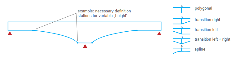
Define the variable progression along an axis. You can use this variables in Superstructure definition, e.g. to control the cross profile variation along the axis. Various Transition Types are available in the Variable definition.
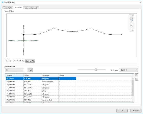
- Variable definition
Using table input - you can assign the value to the station. Transition and Slope parameters define the progression of values between the stations.
Using equation editor - you can write the equation of the variable using the C-Sharp script editor with available System.Math namespace.
Unit type - choose the unit type of the variables. Variable unit will by taken according to the Revit project units.
Scale slider - for better visualisation and input control, you can adjust the vertical scale of the variable using the slider under the preview window.
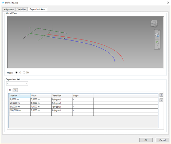
Secondary Axis tab
Define dependent axis relative to the main axis using U (horizontal),V (vertical) Offset values. Offset values can vary along an axis with individual transition type between the stations. While creating new Dependent Axis, all stations of the main axis will be automatically generated.