Multi Girder Bridges
Introduction
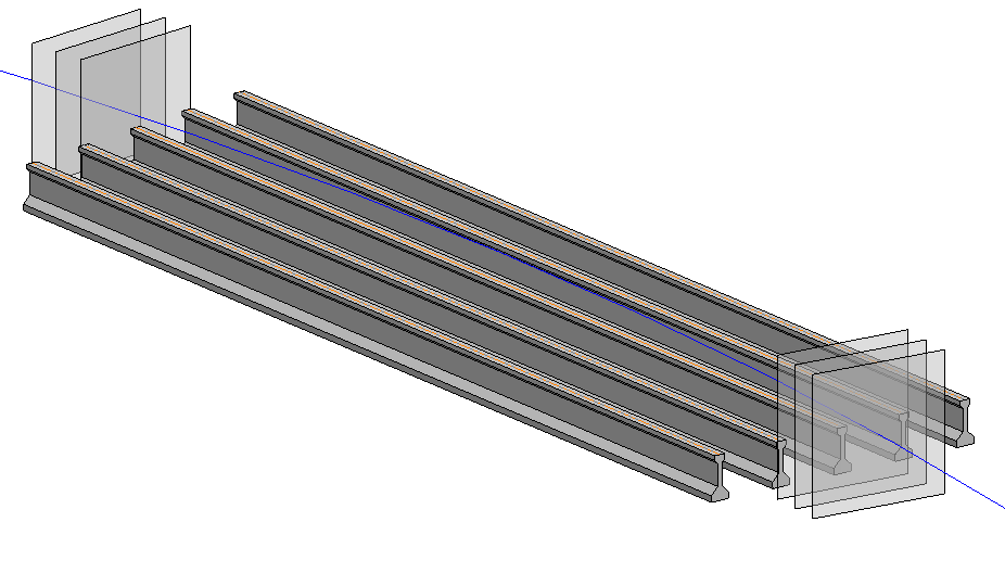
Multi girder bridges are commonly used for fast and easy assembly on site. Prefabricated beams - mostly steel or pre- or post-tensioned concrete - are placed on the bearings or moulded into the cross beams according to the design layout. The concrete slab is poured on top to ensure a solid foundation for the stability of the beams and finishing layers. In case the distance between the beam top flanges is larger than the flange itself - additional formwork is required.
Design challenges
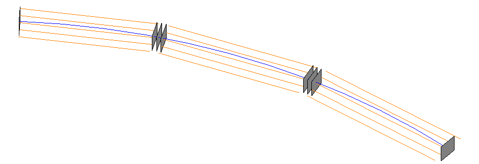
Multi girder bridges are generally assembled with straight beams, even though the deck might be curved. The bridge deck is design based on the axis’s curvature. However, the beams follow a polygonal interpolation of the curve. The axis represents no longer a valid input in terms of the beam geometry. Bridge types such as hollow cast or double t-beam - where superstructure components following the axis curvature - follow the similar approach.
In order to achieve a high level of detail, beams are created as generic families. These families give you great flexibility in geometry creation and Level of Detail. Beams are arranged in spans according to the given layout rule such as maximum distance or fixed number.
Modeling objectives
Logical workflow
Generic design
Adjustable
Variety of bridge types.
Definitions
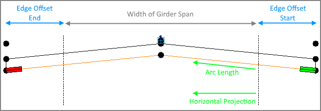
Girder Span – Group of lines, that indicate the primary position of Beams between two placements. Girder Span is created according to the Girder Reference (distribution range) and given layout rule.
Girder Layout – Group of Girder Spans placed on an axis.
Beam (Family) – 3D element placed at the start and the end of each girder. The beams are connected to girder spans and updated after applying changes to the girder layout. Find out more here
Girder Reference – Line(s) with Subcategory “SOFiSTiK_Girder_Reference” in Adaptive Generic Family.
This line indicates the distribution range and vertical position of Beams in each span. The Girder Reference can be a part of Bridge Profile Families (also used for the Superstructure tool) or created as a separate chain of lines.
You can parametrize position and dimensions of Girder Reference using variables or reference to the axis. Find out more here
Workflow
Create an Axis
Create Girder Layout according to Girder Reference, placements and layout rule.
Create Beams on Girder Layout.
Create Deck using Superstructure command.
Create haunch as additional Beam Elements on Girder Span
Families
Beams
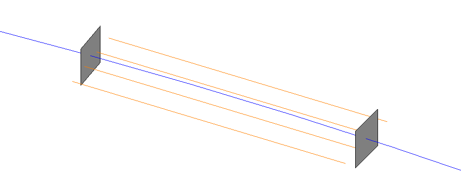
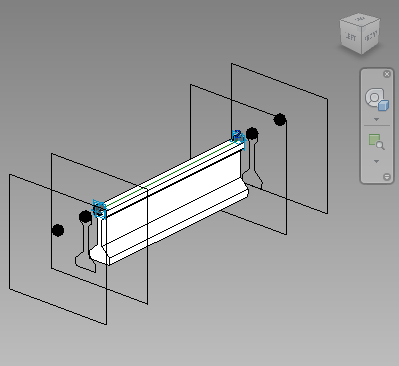
Adaptive generic families with two adaptive points.
Adaptive Points ‘1’ and ‘2’ are placed at the start and at the end of the girder span. Additional Offsets in X/Y/Z directions (see pic) can be defined in the Beam(s) Dialog. You can override offset parameters for each beam individually using the ‘Offset Override’ command.
Find further information to the recommended workflows for Beams customization here.
Girder Reference Family
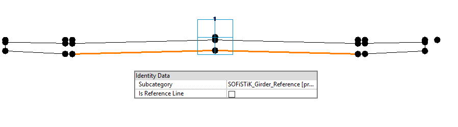
An Adaptive Generic Family with one single Adaptive point and at least one line marked as Girder Reference (highlighted in orange). See also Girder Reference definition above.
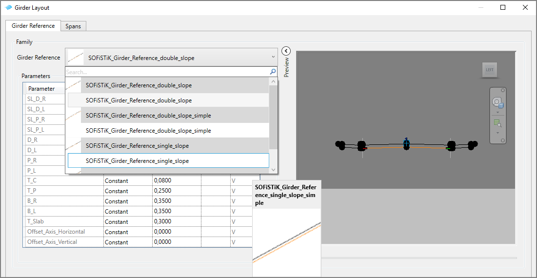
You need at least one family loaded in your project to be able to define a girder layout. All available Girder Reference Families will be listed in Girder Layout Dialog.
Use already provided Girder Reference Families or create your own one(s). Use Mark and Mark Invisible commands to define selected lines in your family as Girder Reference.
Tip
Use Mark tool for lines that are part of the Bridge Profile.
Tip
Use Mark Invisible tool for lines that are not part of the Bridge Profile (used also as Profile for Superstructure command), but are defining the distribution range of the Girder Span. Open or multiple polylines in the Bridge Profile Family can cause problems while generating the deck as superstructure element.
Parametrization
You can define the geometry of a Girder Reference or Beam family with a constant value or assign a variable to the specific parameters. Using the same variable you can create a link between two components. Adjustments of the variable will trigger changes in both elements.


