Generate laying
In SOFiCAD, Layings represent the elements that are counted. These differ in layings in which one can define a distance or a number or both. You can lay out any Barmark View that have already been created using this command. Special forms of laying are variable laying and loose bars. With a specified as value the program can calculate the diameter and number of bars.
laying
 SOF_B_CREATE_LAYING
Command |
Verlegungen |
Tooltip |
Erstellt alle Stabstahlverlegungen |
Ribbon |
None |
Menu |
Bewehrung > Stabstahlbewehrung zeichnen |
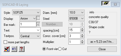
This command can be used to create linear layings, linear sections and pointer-layings. The number of bar steel positions is thus determined.
- Configuration options:
Style: Name of the active graphics configuration. It can be changed or edited using the “Steel Style” menu.
Display: In this menu you can define the type of baseline for the laying. This also determines the functions that are available to the laying.
Mark: The mark for which the laying should be created.
Text: You can enter a text here. You can also choose a predefined text. The predefined texts can be edited using the “SOFiCADB_usr.INI” file (Settings> ini). The semicolon must be removed for the changes to take effect.
Textpos: Defines the placement of the label.
More part lengths: Allows the direct creation of a split laying.
Number: Here you can enter the number of bars to be placed. With linear laying (such as arrow, slash, harp and linear cut), the number is automatically calculated from the distance and the size of the laying.
Distance: defines the distance between the bars.
Concrete cover: defines the distance between the outer contour of the bar and the reference line when working in the formwork edge mode.
Multiplier: Applies a multiplication factor to the number of bars.
View / section: Defines the representation of the bars as lines or as points, the size of which corresponds to the diameter.
Arrangement of the laying by the option “points” on the command bar.

The length of the linear laying is defined by the selection of free points. Once set. SOFiCAD requires the insertion point and the end point of the bars. Here too, various options are displayed on the command bar.

Finally, only one point needs to be entered for the placement of the baseline.

Arrangement of the laying by the option “formwork edge” on the command bar.
When the “Formwork” option is selected, the Autocad cursor activates the selection field for the reference line. We will use the selection field to select the reference line of the laying. SOFiCAD is able to distinguish the side on which the line is selected and thus assigns the concrete cover.
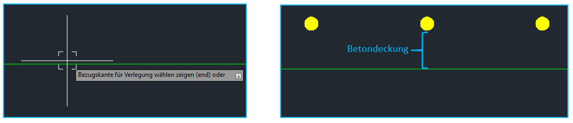

As soon as the reference line is defined, the options for defining the end point of the installation are displayed. These options relate to the position of the bars in relation to the reference line. That is, if we want to place the bars parallel to the reference line, we will use the “Parallel” option. If you want the bars to be orthogonal to the reference line, select the “Vertical” option.
For the definition of the insertion point and the end point of the bars, the process is analogous to that explained in the previous section. (Arrangement of the laying by the option “points”)
Poly laying
 SOF_B_CREATE_LAYING_POLY
Command |
Poly-Verlegung |
Tooltip |
Erstellt Verlegungen im Schnitt in linearer Anordnung entlang einer ausgewählte Polylinie. |
Ribbon |
None |
Menu |
nicht verfügbar |
Creates multiple layings along a polyline.
arrow
 SOF_B_CREATE_LAYING_BV1
Command |
Pfeil |
Tooltip |
Erstellt Stabstahlverlegungen in linearer Anordnung mit Pfeilen für die Bemaßung |
Ribbon |
None |
Menu |
nicht verfügbar |
Creates steel bars in a linear arrangement with arrows for dimensioning
slash
 SOF_B_CREATE_LAYING_BV2
Command |
Schrägstrich |
Tooltip |
Erstellt Stabstahlverlegungen in linearer Anordnung mit Schrägstrichen für die Bemaßung |
Ribbon |
None |
Menu |
nicht verfügbar |
Creates bar steel laying in a linear arrangement with slashes for dimensioning
pointer
 SOF_B_CREATE_LAYING_BV3
Command |
Zeiger |
Tooltip |
Erstellt eine einzelne Stabstahlverlegung |
Ribbon |
None |
Menu |
nicht verfügbar |
Creates a single steel bar relocation
Note
If the steel list is not to be evaluated for the pointer, the number of bars is set to zero via Info / Edit. There is therefore no longer any quantity in the position text. Alternatively, the distance can also be set to zero.
Cut linear
 SOF_B_CREATE_LAYING_CUTLIN
Command |
Schnitt linear |
Tooltip |
Erstellt eine lineare Stabstahlverlegung im Schnitt |
Ribbon |
None |
Menu |
nicht verfügbar |
Creates a linear rebar laying cut
harp
 SOF_B_CREATE_LAYING_HARP
Command |
Harfe |
Tooltip |
Erstellt Stabstahlverlegungen in linearer Anordnung in der Darstellung einer Harfe |
Ribbon |
None |
Menu |
nicht verfügbar |
Creates rebar laying in a linear arrangement in the representation of a harp
cut
 SOF_B_CREATE_LAYING_S1
Command |
Schnitt |
Tooltip |
Erstellt Stabstahlverlegung im Schnitt |
Ribbon |
None |
Menu |
nicht verfügbar |
Creates rebar layingin cut
Cut scheme
 SOF_B_CREATE_LAYING_S1S
Command |
Schnitt Schema |
Tooltip |
Erstellt Verlegung im Schnitt mit schematischer Anordnung der Positionskreise |
Ribbon |
None |
Menu |
nicht verfügbar |
Creates laying on average with a schematic arrangement of the position circles. This can subsequently be combined to create an average laying.


