Intersection with Horizontal Line
 SOF_CM_CONSTRUCTIONMODEVARHEIGHT
Command |
Intersection with Horizontal Line |
Tooltip |
Sets the dependent point at the intersection of a straight line with a horizontal straight line. |
Ribbon |
None |
Menu |
None |
The distance of the coordinate origin to the horizontal straight line can be defined with a variable or formula. The parametric input (formular/variable) is only possible after the definition of the points due to editing.
The points B and C can be also dependent points.
Input
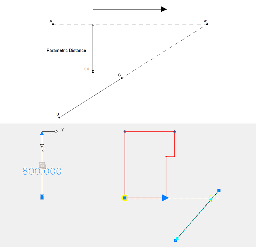
At first a point (dependent point), whose coordinates are parametrically / dependent, has to be defined (point A in the diagram).
Then a cross section point (reference point, point B in the diagram), through which, together with point C, the intersection line is passing, can be input.
Finally, the cross section point (reference point C) is necessary, through which the straight line BC should pass.
If a point which was not yet created as a “cross section point” is to be used for a reference point, then a geometry point can be generated at this position.
Symbolism
The defined references are displayed now symbolically. Here the continuous arrows show the point of the intersection at which the dependent point A lies after the calculation. The distances between reference points to the dependent point (in this case distance to perpendicular and offset distance) are displayed. The labelling of the arrows displays either a numerical value (fixed distance; numerical value is the distance currently shown in the cross section), or a variable name or formula (variable distance).
Reference points are represented by a blue triangle and dependent points by a yellow circle.
Editing
Dependent points are marked by a circle with a diagonal cross within. By left clicking on this symbol, the entire reference object is shown. Then it can be edited according to the following procedure:
The reference points and the dependent point can be moved by left-clicking on the object and by pulling of the point to another (permissible) cross section point position.
Beside the double arrows there is a lock symbol. Due to left-clicking on the lock symbol in this display the field is unlocked for editing. It is possible to switch to the variable reference point mode.
Left-clicking on the lock symbol in this display unlocks the field for editing and switches into the mode for a variable reference point mode.
A further left-click on the lock symbol closes the lock and switches back to the fixed input mode, i.e. the distance is fixed and corresponds again to the actual distance in the master cross section, and the parametric input for the distance is quasi-deactivated.
The switch for changing between absolute and relative references appears only for the distance of perpendicular. If it is set here as ‘rel’ (relative input), it can be also switched consequently between absolute and relative operation for the offset distance.
The green tick confirms the input.
The red cross cancels the dialog.
Deleting
A reference can be selected by left-clicking on the reference symbol and then it can be deleted by using the delete key or with the AutoCAD delete command.


