Structural Line
 SOF_SE_LINE
Command |
Create Structural Line |
Tooltip |
Create structural lines to define beams, linear supports and more. |
Ribbon |
None |
Menu |
None |
 SOF_SE_LINE_M
Command |
Modify Structural Line |
Tooltip |
Modify structural lines. |
Ribbon |
None |
Menu |
None |
Structural lines are linear or curved elements used for a variety of purposes, depending on how their properties are set. Beams, trusses, cables and support conditions can be defined, for example.
Structural lines are written into the structural database (.CDB) during export. From these the program SOFiMSHC then creates linear finite elements (beams, truss elements or cables), or rigid or elastic finite boundary elements for the structural calculation.
Loads can be assigned to structural lines.
A detailed description of these properties can be found in the chapter ‘SLN – Structural line’ and the following chapters of the manual SOFiMSHC.
Note
Each structural element is assigned a local coordinate system. Exported finite elements are created with the same local coordinate systems. This also affects any locally applied loads!
If the local coordinate system of a structural element requires modification, this can be done using the Align Elements command.
The assigned group number can easily be modified via command Assign Group.
For creation of structural lines, the following options are available for use:
Start and End Point
Creates a polygon from a selection of lines. With this input, it is possible to switch between options. The chosen points can be selected from the drawing or input using coordinates. As you type, a preview is displayed in the drawing. The input is ended using the enter key.
Select Objects
Creates a linear element from lines, arcs, polylines and splines. To choose the objects the AutoCAD / SOFiPLUS-X selection methods are available. If a structural area is selected, the elements will be created along the boundary.
Segment on geometric axis
Creates elements with reference to an axis. For this option the following input possibilities are available:
Between all placements: The elements are created from the first placement of the axis up to the last.
Use the segment closest to the picked point: One element is created between the two placements nearest to the picked point on the axis.
The grip points of elements bound to an axis change their type. Instead of the square a small arrowhead can be seen. This arrowhead can be dragged to another placement. This changes the assignment of the element.
Pick Lines or Curves
Creates one element by picking a selection of AutoCAD objects (line, curve, polyline or SPLINE), structural elements or complete geometric axes (without respecting the placements).
Single Element Mode - Polygonal Input
Switches between the polygonal input type and entry of a single element. Single element mode always asks for the start and end point of a new element.
Set Working Plane
Because certain selection options only are available in the current working plane, it is possible to rest the working plane to a user defined position. For this the following options are available:
3Points: The coordinate system is defined using three selected point for the origin, X-axis and Y-axis.
Element: The orientation of the coordinate system is set with the selection of an object.
Database: Restores the coordinate system which is specified in the system information dialog
The working plane remains in place until the command to create the element is closed.
General Tab
Each element is given a name and a number that is shown in the drawing. This is the internal number of the element which is used for identification.
Lines with the number zero cannot have loads applied to them.
The group number is handled as a master number. It is used for all generated elements (beams, springs, boundary elements etc.) where nothing is defined in the corresponding tab. The group number for beams can be defined here only.
The support width (for punching design) is used as the support width for punching design in the design program BEMESS.
Beam/Cable Tab
In this tab there is the possibility to generate linear finite elements from structural elements. In the element type section it is possible to choose (or to define) the properties of the line. If a haunched section is to be generated, two different cross sections can be specified or created for the two ends. Please note that only similar shaped sections can be used in this case, although they may have different dimensions. This possibility is not available for use with truss and cable elements.
If a beam should be placed as an eccentric beam or pile, this eccentricity must be defined within the cross section. The
definition of a Pile can be done by ticking the variable bedding tickbox and selecting a bore profile.
Using the FE Mesh Method options allows to control the behaviour, when a structural line is intersected with other structural elements:
Automatic Meshing: Multiple short beams are created from the structural lines. The created elements will be integrated into the area mesh.
Structural Area Independent Meshing: Now individual elements that are created from the structural lines are not integrated into the area mesh.
Generate One Element: A single element is created from a structural line and is not integrated with the area mesh. This option is used for the creation of cable elements.
Generate one Element with Output Sections: A single element with output sections is created from a structural line and is not integrated into the area mesh.
Using one or a combination of the Intersection Properties allows to disable the intersection with the respective structural element types.
Specifying one of the Element Length options means that each structural line can be assigned its own mesh density. These elements are then meshed with settings that are independent from those defined in the export dialog box.
Beam Hinges Tab
A hinge can be defined at a beam’s start and/or end points. If the option work law is also activated, an implicit beam hinge can be assigned.
Similar to the definition of hinge conditions at the start and the end of the structural line hinge conditions can also be defined to adjacent members (relative to crossing structural members). Such kind of input can be used to model the connection between a rafter and the purlin in roof constructions, in order to keep moment forces within the rafter and to prevent an input of torsional moments into the primary bearing construction.
Note
Beam hinges have to be from type work laws for implicit hinges.
Support Conditions Tab
Support conditions (rigid supports) can be created from structural lines here.
There is a distinction between local and global support directions. With the All tickbox, all supports for that row can be
activated or deactivated. Mixing of global and local supports is available only in a limited manner. For example, if a global
direction support is activated, the local direction supports will no longer be available, however local moment supports will be there.
Options that are unavailable are greyed out by the program.
Bedding Tab
Elastic supports for the structure can be defined here. Entries can be created or deleted by using the buttons at the top of the dialog box. If entries are made in the editing fields, boundary elements are created upon export. If a material with bedding properties or work laws are assigned instead, these supports are exported in the form of single node support springs. Each bedding can be assigned its own influence width and a factor at the beginning and the end.
A bedding can be defined to fail in tension in a non-linear calculation (specify Yield Stress = 0 in the material bedding properties). These effects can be considered only when using a non-linear calculation.
The dimensions out of this tab is not used for punching design. To define the dimensions for punching design use tab General.
Lower/Upper Wall Tab
Elastic support conditions for structural lines can be defined here. The spring values are not directly entered, but calculated from the geometry of the corresponding elements and their materials. The values for the elastic supports are determined and written directly to the structural database (.CDB) when the drawing is exported. After the export, this input is no longer available for modification. The calculated values are entered into the Bedding tab when the drawing is exported.
When entering data in the lower part of the dialog box, the input is used to approximate the spring stiffness of an equivalent wall.
The End fixity (remote) describes the degree of fixity at the other end of the wall. The value 0 defines a pinned support, while
the value 100 defines a rigid support.
The calculation of the wall is done assuming a wall width of 1m.
The value in the structural database (.CDB) is calculated as follows:
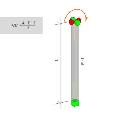
Rotational spring at the opposite end:
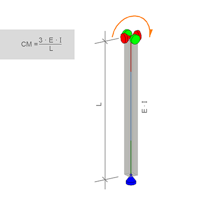
Rotational spring with hinged supports at the opposite end:
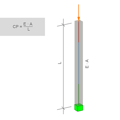
Vertical spring:
The dimensions out of this tab is not used for punching design. To define the dimensions for punching design use tab General.
Interface Elements Tab
On this tab (available only in 2D Frame and 2D Plane systems) the properties of special interface elements can be defined. The side on which the interface element is defined is marked by a second line.
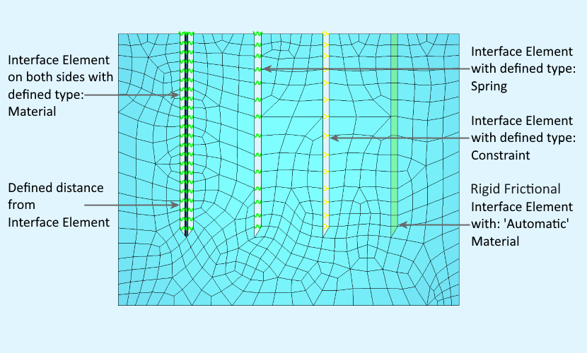
A detailed description of these input possibilities can be found in the chapter ‘SLNS – Supports and kinematic couplings on a SLN’ of the manual SOFiMSHC.
Loads Tab
On this tab (available only when modifying an existing element), loads which are applied directly to the line can be defined or modified.
The load Geometry field can be used to define the position of the load on the line. It is possible to assign an absolute value
or to select as ratio of element length. Values which are unavailable for editing are locked with a lock symbol. The other
values can be modified.
The load Eccentricity field can be used to define the position of the load relative to a point within the section of the line.
A detailed description of the load possibilities can be found in the chapter ‘LINE,CURV – Free Line Loading’ of the manual SOFiLOAD.


