Create Objects between Placements
 SOF_CABD_MAKE_PATH
Command |
Create Objects between Placements |
Tooltip |
Create elements between two placements along an axis. |
Ribbon |
None |
Menu |
None |
 SOF_CABD_EDIT_PATH
Command |
Edit Objects along Curve |
Tooltip |
Modifies the number of generated elements along the path. |
Ribbon |
None |
Menu |
None |
 SOF_CABD_UPDATE_PATH
Command |
Update Objects along Curve |
Tooltip |
Distributes the source elements back to the path. |
Ribbon |
None |
Menu |
None |
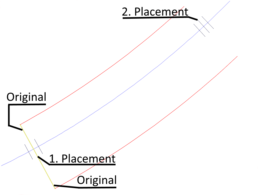
Command to create elements along an axis. The elements are distributed between two placements to be displayed. The number of elements to be generated or a distance between the elements can be defined.
The program creates a distribution line bound to the axis and bordered by two placements. The length of the distribution line is taken from the distance of the picked placements.
The elements are created along the distribution line and refer to it. The distance of the first element to the distribution line is taken into account.
The created elements can be changed independently of the source element. If the source element changes, this does not initially affect the other elements.
To reallocate the properties of the source element back to the elements along the distribution line one can use command Update Objects between Placements.
If the geometry of the axis or the location of the placements at the beginning or end of the distribution line changes, the distribution line and the created elements are adjusted, too.
With command Edit Objects between Placements the number of the created elements can be changed. In this case the elements in the path are also re-adapted to the source element.
If the dialog is only opened to check the distribution rule, the elements in the path are not modified.
For creation of the elemente, the following options are available for use:
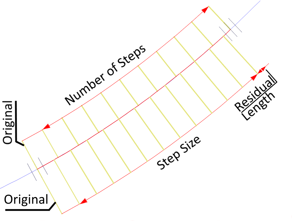
Fixed Number of Steps
The first element is the source element. It is not counted. The last element is generated exactly according to the lenght of the distribution line.
Step Size
The first element is the source element. Thereafter, elements are created at the given distance to the length of the distribution line. If the distribution length is not exactly divisible with the given distance, a residual length remains.
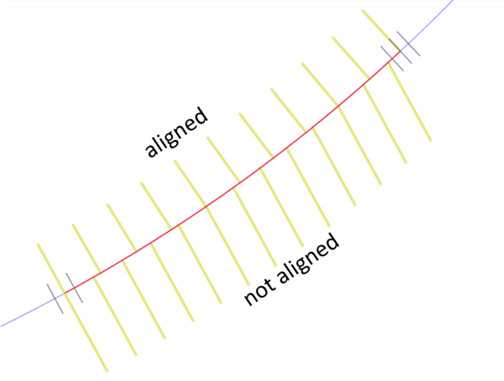
Align items to Path
Specifies whether to align each item to be tangent to the path direction. Alignment is relative to the first item’s orientation.
Some hints for the creation:
If two distributions are to be made one behind the other, it makes sense to create an auxiliary placement that terminates the first distribution line.
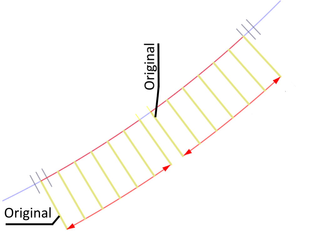
It makes sense to create the source in the first placement. Thus, the elements on the path automatically adapt to an axis change (radius of the axis, rotation of the placement).
A source object can only be assigned to one distribution line.
Allowed elements:
Supported elements are structural points, structural lines and drawn tendon elements in shell systems.


