Composite Bridge
Introduction
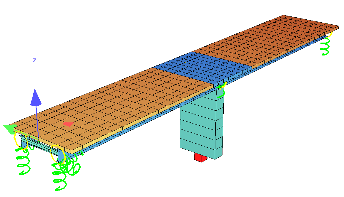
This tutorial deals with a simple 2-span composite beam bridge. The analytical model of the bridge consists of two composite beam sections connected with a concrete slab and steel cross beams. This tutorial is based on Eurocode DIN EN 1994.
All necessary informations regarding the bridge dimensions (drawings) and properties can be found
in the .zip file. There you will find a .pdf file with the necessary informations and
drawings.
In order for you to follow the work-flow more easily, we have split up the data files according to the different chapters. This enables you to start in the middle of the tutorial if necessary. The idea of this tutorial is to guide you through a simple composite bridge project and introduce the general work-flow showing the necessary program tools and functions. All steps like modelling, loading, traffic, combinations etc.. are simplified.
Note
A basic SOFiSTiK knowledge is required for this tutorial. The standard workflow is explained inside the General Workflow description. Inside this tutorial we show only the project specific workflows, which are different from the basic workflow.
Objectives
Starting a new project
Define Materials
Define Cross Sections
Generate System and Loads inside SOFiPLUS(-X)
Linear analysis
Live load analysis
Construction Stages
Design
Project Description
Note
If there are any hints of new tasks that have to be modified manually (new tasks named Text Editor (Teddy)) you find further information’s directly in those tasks. Please open data files related to the chapter.
Bridge Axis
Spans [m] |
- |
20.0 |
- |
20.00 |
- |
Stations [m] |
0 |
- |
20.00 |
- |
40.00 |
Bridge Materials
Number |
Title |
Strength |
|---|---|---|
1 |
Steel composite beam |
S 355 |
2 |
Reinforcement steel composite beam |
B 500 |
3 |
Concrete composite beam uncracked |
C 30/37 |
4 |
Concrete composite beam cracked E = 300 MPa |
C 30/37 |
6 |
Steel cross beam |
S 355 |
20 |
Concrete pier |
C 30/37 |
21 |
Reinforcement steel pier |
B 500 |
40 |
Concrete slab weightless GAM = 0.0 kN/m³ GRP 40 |
C 30/37 |
41 |
Reinforcement steel slab GRP 40 |
B 500 |
50 |
Concrete slab weightless GAM = 0.0 kN/m³ GRP 50 |
C 30/37 |
51 |
Reinforcement steel slab GRP 50 |
B 500 |
Cross sections
Number
|
Title
|
Dimensions
|
|---|---|---|
1
|
Composite section 1 left
|
hs = 1000 mm hc = 300 mm
Materials No 1, 2, 3
|
21
|
Composite section 21 left support
|
hs = 1000 mm hc = 300 mm
Materials No 1, 2, 4
|
2
|
Composite section 1 right
|
hs = 1000 mm hc = 300 mm
Materials No 1, 2, 3
|
22
|
Composite section 21 right support
|
hs = 1000 mm hc = 300 mm
Materials No 1, 2, 4
|
3
|
Pier
|
b x h = 1200 x 4200 mm
Materials No 20, 21
|
6
|
Cross beam
|
IPE 400
Material No 6
|
Construction stages
Stage Number |
Title |
|---|---|
9 |
Formwork steel beams |
10 |
Steel beams self weight |
39 |
Cast bridge deck GRP 40 (midspan) and activation of wet concrete self-weight |
40 |
Bridge deck GRP 40 hardened |
45 |
Creep + Shrinkage in construction for 28 days |
49 |
Cast bridge deck GRP 50 (support) and activation of wet concrete self-weight |
50 |
Bridge deck GRP 50 hardened |
55 |
Creep + Shrinkage in construction for 28 days |
60 |
Additional dead load (adl) e.g. for pavement and railing |
65 |
Creep + Shrinkage until t=infinity |
Starting a new project
First we create a new SSD project and save it inside a project directory on your local computer. For further information see chapter Start New SSD Project in General Workflow description.
Defining materials
Generate all necessary materials listed above. Follow the procedures explained in chapter Material Definition in General Workflow description.
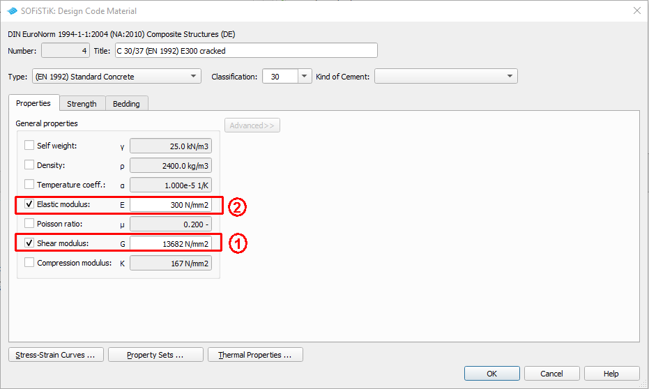
Important
In case that you want to reduce the elastic modulus E, please take into account hat the shear modulus G will be reduced automatically as well. First set the shear modulus G to fix and then change the elastic modulus E. See figure below how to do it in dialog “Design Code Material”:
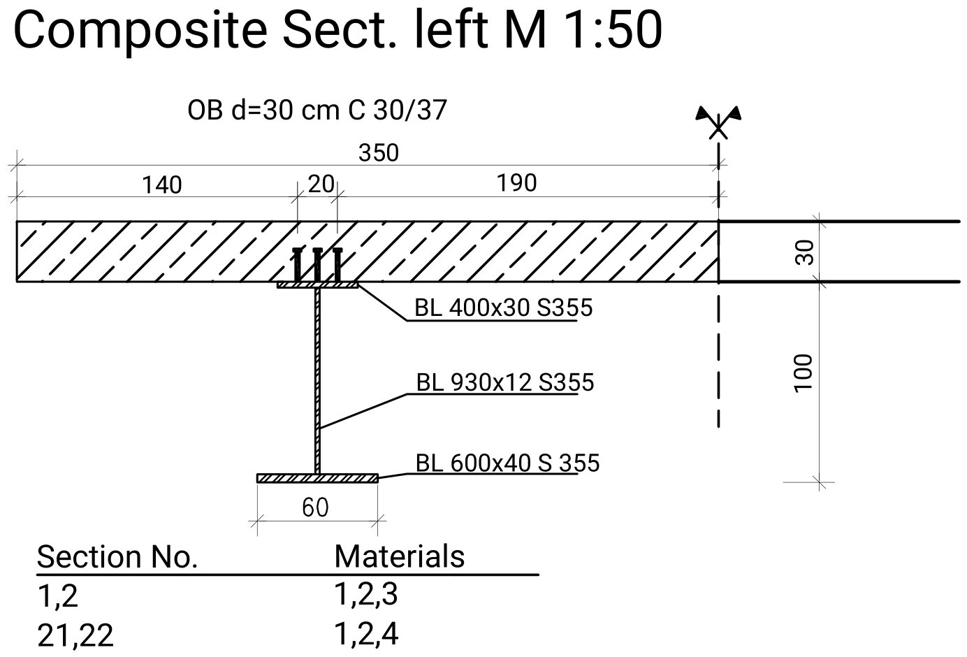
Defining Cross Sections
For composite beams we must define some special composite cross sections. This can be done very easy inside SOFiPLUS(-X) with the Cross Section Editor. To define a composite cross sections the following steps are necessary
Make sure all necessary materials are defined first
Cross section geometry should be clear
Define variables to be used inside the cross section first within the axis definition
Define all necessary cross section construction stages and link the numbers to the overall construction stage sequences
The following video shows the generation of cross section 1 from this tutorial example.
Title: Create a composite cross-section | Quality: 1080p HD | Captions: English

For the cross beams and the pier use standard cross section types. Follow the procedures explained in chapter in Cross Section Definition in General Workflow description.
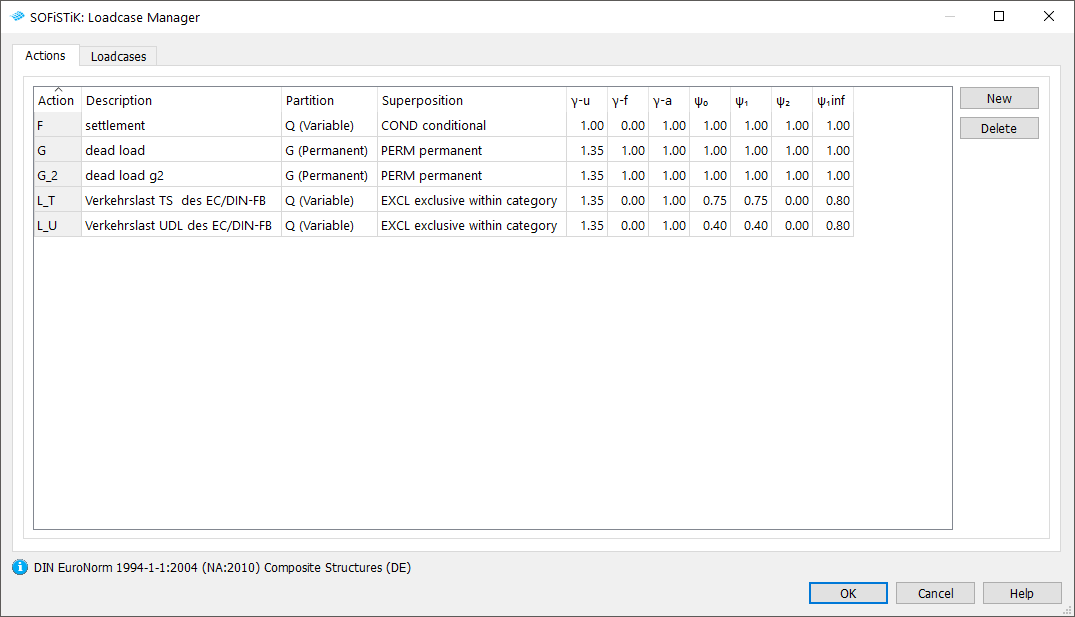
Actions
Before we define any load, we must define all necessary actions within the SSD ” Action Manager”. In our bridge example we need the following actions. (click on the figure to see it in full size).
System Generation in SOFiPLUS(-X)
The bridge geometry we will be defined using the CABD concept inside SOFiPLUS(-X). For that we will work through the following steps:
Define main bridge axis
Define placements along the bridge axis
Define secondary axes
Define variables
Generate structure elements (lines and areas) representing the main bridge construction
Generate cross beams and connect them to the existing placements
Use the Cross Members Editor to generate the support construction containing springs and couplings
Make a final check of the system and align elements if necessary
The following video will show the main steps to generate the system.
Loads
The loads will be defined inside SOFiPLUS(-X). First define the necessary loadcases inside the Loadcase Manager. Then create the loads and allocate the loads to the loadcases.
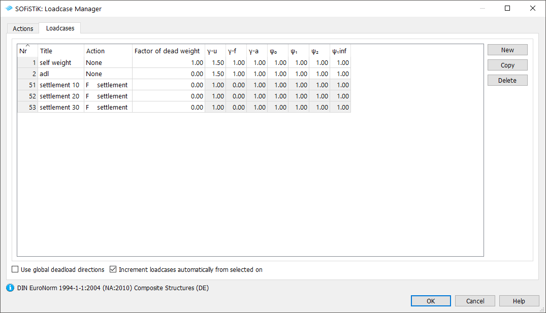
Follow next steps to open the ‘’Loadcase Manager’’ dialog:
After defining the load cases we generate the loads in SOFiPLUS(-X). First we select an element related line load. Defining the load we select the structural lines and the edges of our bridge deck and define a line load of \(10~kNm\). An additional dead load (adl) for pavement is defined as a structural area load with \(2.5~kN/m^{2}\). In every support axis we define a settlement \(w_{zz} = 10~mm\) and save the loads within the load cases 51 to 53. In this little tutorial we will not apply any temperature load.
Warning
Load cases which will be used later on inside the CSM should be saved within the action container NONE. With this concept the load cases will not be used twice in case the user defines his own combination rules using actions only!
Please see also the chapter Define Actions and Loads in General Workflow description.
Linear Analysis
As we use a model which contains both beam and shell elements, we CANNOT use the standard task “Linear Analysis”. Instead we must add some commands to switch of the shell element stiffness in the longitudinal bridge direction. To do so, simply generate a task “Linear Analysis”, as usual with the standard graphics deactivated, and convert it with the command “Convert to User Text”. Now open the Text Task and make the changes as shown below:
+PROG ASE $ Linear Analysis
HEAD Linear Analysis
PAGE UNII 0
CTRL OPT SOLV VAL -                  $ Solution of the system

$ Add the following line to take care of shell element stiffness
GRP2 NO 40,50 QUEA 0.01 QEMX 0.001   $ Reduction of QUAD stiffness in longitudinal direction

LC 1,2,51,52,53
END
Note
This input reduces the elastic stiffness for shell elements. Once added this stiffness correction is saved and will be used again in the next PROG ASE module, even if you miss the input GRP2. In that case you will get a warning. We recommend to set the GRP2 record everytime in the PROG ASE module.
After this task it may be convenient to add a task “Interactive Graphic” to plot the results of the bending moment MX for one beam sequence to compare the results. Please note, that the system self weight and the additional dead load will be used later on in the construction stage manager as well.
Please see also the chapter Linear Analysis in General Workflow description.
Generate Envelope from Traffic Loads
As already explained in the general workflow it is necessary to run at least one linear load case before evaluating the traffic loads with the influence line method. We recommend to do this analysis before the construction stage analysis to use the full developed stiffness matrix from the complete bridge.
Note
The stiffness effects of the shell elements were already used within the linear analysis. The following influence line evaluation will therefore be processed on that basis. Additional settings are not necessary.
For a general description of the input workflow please see also the chapter Traffic Loads in General Workflow description. For our little example we have a two lane bridge with a total width of 6.0 m.
First you select an existing bridge axis and define the width of the traffic lane and bridge. The program will automatically generate all possible lanes.
Next you define the load trains and the desired results. In our case we are interested only in the beam results for further design of the composite cross sections.
For the results it is necessary to define different load groups and evaluation cases. Usually it is convenient to separate the results for tandem axes and udl loads. The evaluation results will be saved again in predefined action container.
The loads on the footway will be defined as an extra evaluation case inside the UDL load group. In that case we need special combinations from UDL and Footway loads. Simply use the combination button inside the dialogue and generate the combinations.
After the input is correct and finished you may close the dialogue and process immediately the analysis. Again we recommend to add a task “Interactive Graphic” to display the important results.
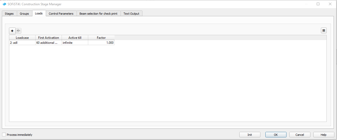
Define Construction Stages
For composite bridges the contruction stages are especially of great importance. Besides the different beam element stages, we must take into account the stages inside the cross sections as well as the stages of the concrete work. In our example we like to have the precamber shape of our steel beams, and we want to take care of two major concrete work steps. In a first stage (CS 40) the concrete bridge deck is cast over the midspan area of both spans. After that the concrete is cast over the mid support in CS 50. For checking reasons we will also apply a construction stage, where we look at the time, when the concrete has hardened. Please see the table Construction Stages above.
For our example the following input must be done inside the task “CSM - Construction Stage Manager” (click on the figures below to see the figures in full size).
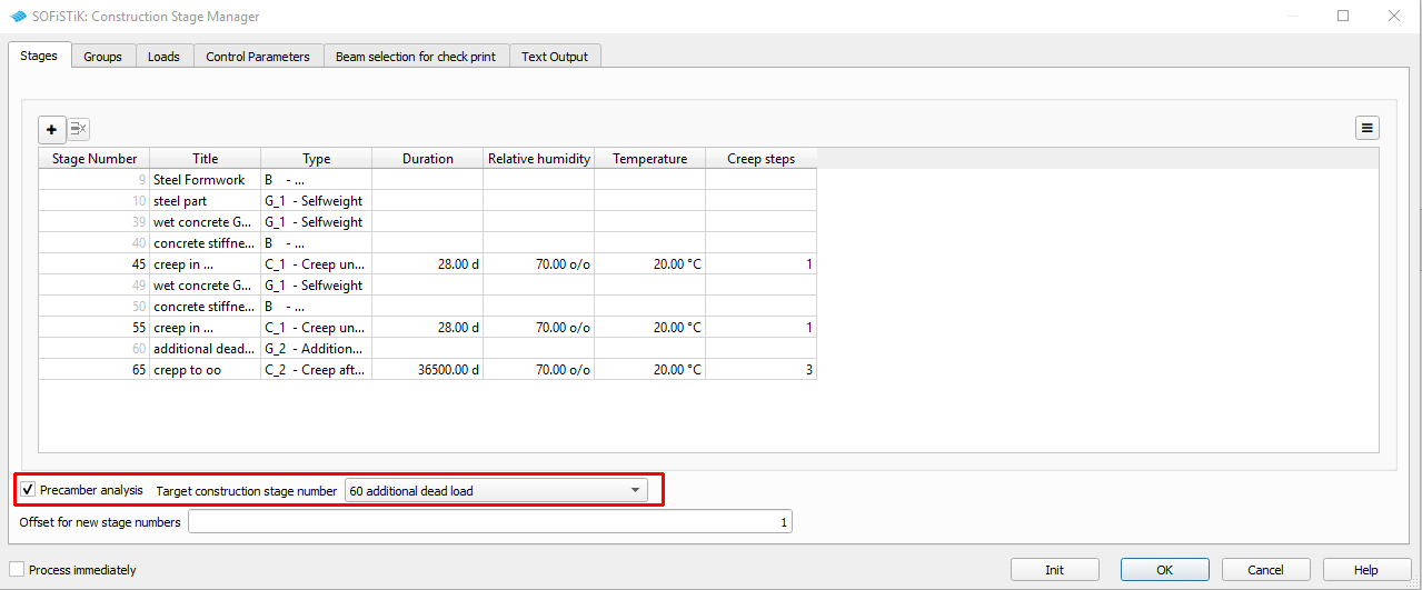
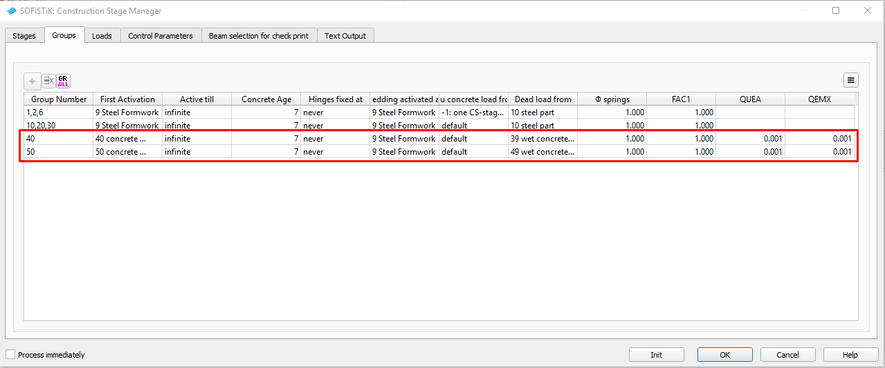
For further explanations please see also the chapter Construction Stages in General Workflow description and our csm_1.pdf manual.
Combinations
Usually we are using the combination feature from CSM-DESI. Please see the chapter Combinations and Superpositioning in General Workflow description. In this example we only want to have one single design combination. For that reason we will not use the CSM-DESI function, but write a short input script manually.
!#!Chapter Define Action Container
+PROG SOFILOAD urs:19.3
HEAD Definition of Actions - temporary superposition
$ The following actions Y_ are special container to save results
$ and will be used only for intermediate combinations
$ Please don't use these actions in another context
$ACT Y_1 GAMU 1.0 0 1 1 1 SUP EXEX Titl  ' rare without gpc'
$ACT Y_2 GAMU 1.0 0 1 1 1 SUP EXEX Titl  ' nonf without gpc'
$ACT Y_3 GAMU 1.0 0 1 1 1 SUP EXEX Titl  ' freq without gpc'
$ACT Y_4 GAMU 1.0 0 1 1 1 SUP EXEX Titl  ' perm without gpc'
$ACT Y_5 GAMU 1.0 0 1 1 1 SUP EXEX Titl  ' L_5  without gpc'
$ACT Y_6 GAMU 1.0 0 1 1 1 SUP EXEX Titl  ' L_6  without gpc'
$ACT Y_7 GAMU 1.0 0 1 1 1 SUP EXEX Titl  ' L_7  without gpc'
$ACT Y_8 GAMU 1.0 0 1 1 1 SUP EXEX Titl  ' L_8  without gpc'
$ACT Y_9 GAMU 1.0 0 1 1 1 SUP EXEX Titl  ' 1.0* without gpc'

ACT Y_D GAMU 1.0 0 1 1 1 SUP EXEX Titl  'Design w/o ACT G,C'
END

!#!Chapter Combination and Superpositioning
+PROG maxima urs:18.2 $ULS Combination without ACT G and C
HEAD ULS Combination without ACT G and C

!*!Label ULS Combinationrule
COMB 101 EXTR desi BASE - TYPE Y_D  TITL 'Design Combination'
$ Select Actions
 ACT F
 ACT L

!*!Label  Superpositioning
SUPP 101 extr mami etyp beam type N,Vy,Vz,Mz,My,Mt      LC 3001     $LC 3001-3012
$SUPP 101 extr mami etyp quad type N,Vx,Vy,Mxx,Myy,Mxy  LC 3013     $LC 3013-3024
SUPP 101 extr mami etyp spri type P                     LC 3025     $LC 3025-3036

END
Note
You may use the input script “Desi-Max” from the General Workflow description and copy and paste the input form the automatic generated _maxi.dat file.
Design
The design of composite beams must be done in different design steps inside the module AQB.
Again it is important to use this module for a combination of all load cases used during the
construction stages. This is necessary because only the module AQB is able to use the correct
internal forces and moments corresponding to the right cross section. All results applied on the
final construction are acting on the same cross section properties and are combined before.
Therefore we will use the action container Y_D for all traffic and variable loads.
For the ULS design of composite sections the following design checks are necessary according to EN 1994-2:
resistance of cross-sections (see 6.2 and 6.3)
resistance to lateral-torsional buckling (see 6.4)
resistance to shear buckling and in-plane force applied to webs (see 6.2.2 and 6.5)
resistance to longitudinal shear (see 6.6)
resistance to fatigue (see 6.8).
Inside SOFiSTiK we do the design check according to the cross sections with module AQB:
- Cross section design: record DESI ULTI AMAX FIX SCL 3 SMOD NO
- design of shear studs with check total bond force: record STRE K F
- Design of c/t ratio according to section class 2 or 3: record STRE C
Note
The resistance due to shear buckling and in-plane force cannot be checked on cross section level. This has to be done in a shell element system.
Basically the design process for sections follows always the same principle.
define
ECHOoptions for control of output extentdefine controll parameter
CTRL, such as include reinforcement into the cross section propertiesSelect the beam elements with the
BEAMcommand for which you want to do the design checks for. Link the beam elements to the corresponding construction stagesSelect all design loadcases and link them to the corresponding cross sections
Define design combinations
COMBStart the design with the corresponding command, e.g.
DESI
An example of the input procedure for any cross section design is listed below:
+PROG AQB  $Design ULS
HEAD Design ULS

!*!Label Prepare Design
$ 1. ECHO Options
ECHO TABS               $ tabular summary
ECHO FULL no            $ no output
ECHO COMB,FORC FULL     $ forces of single load cases and combination loadcases
ECHO DESI,USEP FULL     $ design results
ECHO SHEA      NO       $ shear design

$ 2.controll parameter
CTRL SVRF   1.00000 $ take into account reinforcement for C+S
CTRL REIN FIX       $ fix reinforcement
CTRL VM - 1.0       $ treatment of torsional moment as normal force


$ 3. Select beam elements for design including cross section stages
$ the section experiences 3 modifications in stages 1,40,50. => cs0, cs1, cs2

BEAM FROM GRP 1,2 X - CS auto
$BEAM FROM 20006 X - CS auto

$ 4. select loadcases with actions and cross section reference
$ Chart of the loadcases used in the CSM
LC  5??? $ all 5000...GPC-loadcases as in the LC-list in file _csmlf.dat
LC  6??? $ all 6000...AQB creep inner EIGE stresses
LC      TYPE 'Y_D ' CST   70

!*!Label ULS Design Cross Section
$ 5. combination for ULS design including load case storage number LCST
COMB EXTR MAXD SCOM MY LC1 G LC2 C LC3 Y_D LCST 2900 Titl 'MAXD MY: G+C+Y_D'
COMB EXTR MIND SCOM MY LC1 G LC2 C LC3 Y_D LCST 2901 Titl 'MIND MY: G+C+Y_D'

$ 6. ULS design - check cross section
$ Plasticity control for steel and composite sections
$ SCL 3 = Compressive  strain  is  limited  to  the  yield value
DESI ULTI SCL 3 SMOD NO
END
Resistance of Cross Section
The cross section resistance will be checked with the command:
PROG AQB
...
CTRL REIN FIX
...
DESI ULTI SCL 3 SMOD NO
END
Very important for the composite section design is the option CTRL REIN FIX. We recommend to use this option always, because the reinforcement in the concrete slab will be fixed. Now the cross section resistance will be checked without any increase of reinforcement. Usually in composite bridge design the amount of reinforcement in the concrete slab is defined by the minimum reinforcement due to the code and the maximum possible reinforcement due to the slab geometry.
The option SCL controls the strain distribution inside the cross section for the design check. SCL 3 means, that steel members of the cross section remain always linear elastic under compression stresses. For further explanation including the other options please see the aqb_1.pdf manual in chapter 3.15-DESI.
Resistance of Longitudinal Shear
The resistance for the longitudinal shear is not checked directly. The program evaluates the total bond force between concrete and steel with the command:
PROG AQB
...
STRE E F
END
According to the EN 1994-2 chapter 6.6.2.1 (2) the uncracked concrete material may be used for the total bond force design check. Therefore we change temporarily the material properties back to the uncracked condition. Then we perform the design check and change back the materials to the cracked condition for consistency reasons.
The total bond force is printed in a table called “Stresses” inside our Report Browser. For every beam section the normal forces are printed for the different materials. You will find this value in the last column of the table with first header \(N[kN]\). The Total Bond Force displayed in WINGRAF is derived from the difference of normal forces in adjacent beam sections.
The value \(T[kN/m]\) represents the total shearing force.
c/t Ration in Steel Section
The c/t ratio is checked with the command:
PROG AQB
...
STRE C
END
Within the output you will see a table called “Plate Slenderness c/t”. Inside this table the slenderness check is made for every beam section and every part of the cross section if under compression. Results are plotted for the single plates as well as for the extremum of the beam section.
Documentation
For the final documentation, you can collect all single reports and generate a complete document. Please read the chapter Generate Report in the General Workflow description.


