Concrete Slab Bridge
Introduction
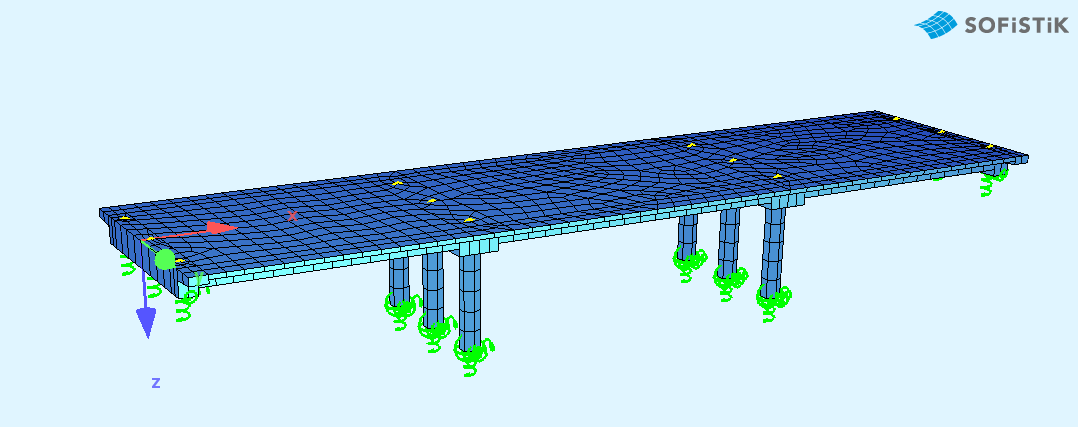
This tutorial deals with a simple 3-span concrete slab bridge. The analytical model of the bridge consists of shell elements and beam elements for the columns.
Note
A basic SOFiSTiK knowledge is required for this tutorial. The standard workflow is explained inside the General Workflow description. Inside this tutorial we show only the project specific workflows, which are different from the basic workflow.
Objectives
Starting a new project
Define Materials
Define Cross Sections
Generate System and Loads inside SOFiPLUS
Linear analysis
Live load analysis
Construction Stages
Design
Project Description
In order for you to follow the work-flow more easily, we have split up the data files according to the different chapters. This enables you to start in the middle of the tutorial if necessary. The idea of this tutorial is to guide you through a simple RC (Reinforced-Concrete) bridge project and introduce the general work-flow showing the necessary program tools and functions. All steps like modelling, loading, traffic loads, combinations etc. are simplified.
Note
If there are any hints of new tasks that have to be modified manually (new tasks named “Text Editor (Teddy)”) you find further information’s directly in those tasks. Please open data files related to the chapter.
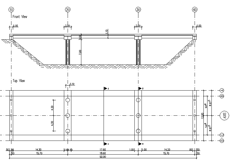
Bridge Axis:
The bridge has 3 spans with overhangs at the beginning and at the end of the bridge.
Spans [m] |
- |
0.50 |
- |
- |
15.70 |
- |
- |
19.60 |
- |
- |
15.70 |
0.50 |
Stations [m] |
10.00 |
10.50 |
11.50 |
25.20 |
26.20 |
27.20 |
44.80 |
45.80 |
46.80 |
61.00 |
61.50 |
62.00 |
Bridge Materials:
For the bridge we will use the following materials.
Number |
Title |
Strength |
|---|---|---|
1 |
Concrete bridge deck |
C 40/50 |
2 |
Reinforcement steel deck |
B 500 |
11 |
Concrete Pier |
C 40/50 |
12 |
Reinforcement Steel Pier |
B 500 |
Code
This tutorial is based on the Eurocode EN 1992-2004
Starting a new project
First we create a new SSD project and save it inside a project directory on your local computer. For further information see chapter Start New SSD Project in General Workflow description.
Defining materials
Generate all necessary materials listed above. Follow the procedures explained in chapter Material Definition in General Workflow description.
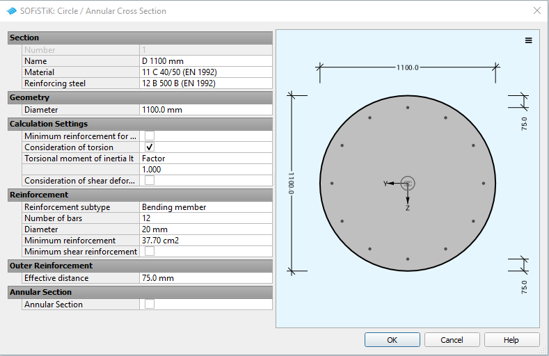
Defining Cross Sections
In this project we have only one standard cross section for the pier. Please generate a new rectangular cross section with the dimensions and material properties listed above. Follow the procedures explained in chapter in Cross Section Definition in General Workflow description.
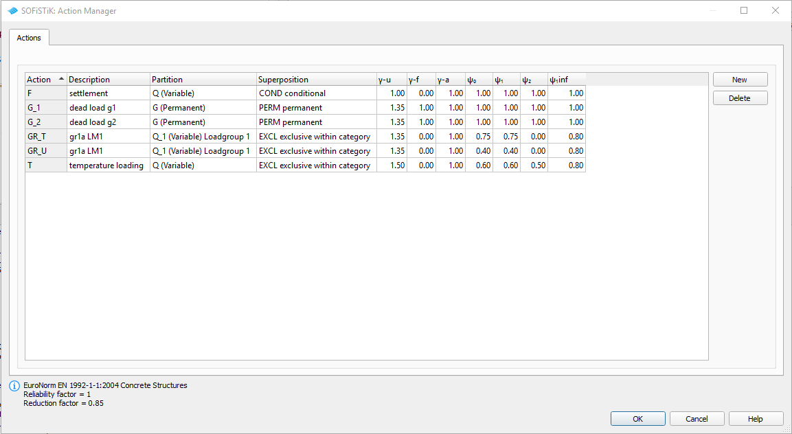
Actions
With the new Action Manager we define all necessary actions before we start the system generation inside SOFiPLUS.
System Generation in SOFiPLUS
The bridge geometry we will be defined using the CABD concept inside SOFiPLUS. For that we will work through the following steps:
Define main bridge axis
Define placements along the bridge axis
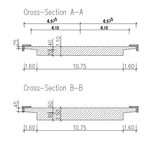
Generate structure areas with varying thickness representing the main bridge deck.
Use the Cross Members Editor to generate the support construction and piers containing springs and couplings.
Make a final check of the system and align elements if necessary
Generate Bridge Axis
Generate the main bridge axis including secondary axis with the geometry information from the project description. For further information see chapter Start New SSD Project in General Workflow description.
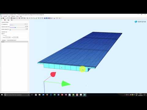
System Generation
The following video will show the system generation workflow.
Additional System Elements
Corresponding results from different elements, like support springs, are sometimes important and necessary. To get these information we must use additional system elements called “Result Sets = RSET”
Note
Currently it is not possible to define results sets inside SOFiPLUS. This must be done with an additional SSD task “Text Editor (TEDDY)”
Behind the “GUI for Model Creation (SOFiPLUS-(X))” task we create a new “Text Editor (TEDDY)” task . Open this task and add the following input:
+PROG SOFIMSHA
HEAD CREATE RESULT SETS
SYST REST    $ KEEP SYSTEM AND ADD ELEMENTS
CTRL REST 2  $ KEEP LOADS INSIDE THE DATABASE
RSET DEL     $ Delete all RSET's before recreate them.

RSET ID 'SPRI' TITL 'SPRINGS'

RSET ID 'PX' SET SPRI_RES ITEM P NO 20201  TITL 'PX'
RSET ID 'PY' SET SPRI_RES ITEM P NO 20202  TITL 'PY'
RSET ID 'PZ' SET SPRI_RES ITEM P NO 20203  TITL 'PZ'

RSET ID 'MX' SET SPRI_RES ITEM M NO 20204  TITL 'MX'
RSET ID 'MY' SET SPRI_RES ITEM M NO 20205  TITL 'MY'
RSET ID 'MZ' SET SPRI_RES ITEM M NO 20206  TITL 'MZ'

END
Warning
With the commands “SYST REST and CTRL REST 2” you will add new elements to the system. In case you recalculate your project without a new system generation from SOFiPLUS you will get an error message, that some elements are already inside the data base. You try to create the same elements twice. So be careful with that.
Loads
In our bridge example we need the following load cases and define all of them inside SOFiPLUS with the Loadcase Manager.
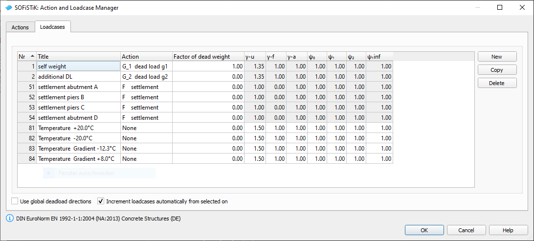
For additional dead loads we will apply a uniform distributed load of 2.5 kN/m² on all areas. In every support axis we define a settlement wzz = 10 mm and save the loads within the load cases 51 to 53. For the temperature loads we generate 4 loadcases 81 to 84 containing the basic temperature loads
LC |
Action |
Designation |
|---|---|---|
81 |
NONE |
constant temperature DT = + 20°C |
82 |
NONE |
constant temperature DT = - 20°C |
83 |
NONE |
temperature difference DTZ = -12.3°C |
84 |
NONE |
temperature difference DTZ = +8.0°C |
For further processing including the necessary temperature combinations please see the chapter Define Actions and Loads in General Workflow description.
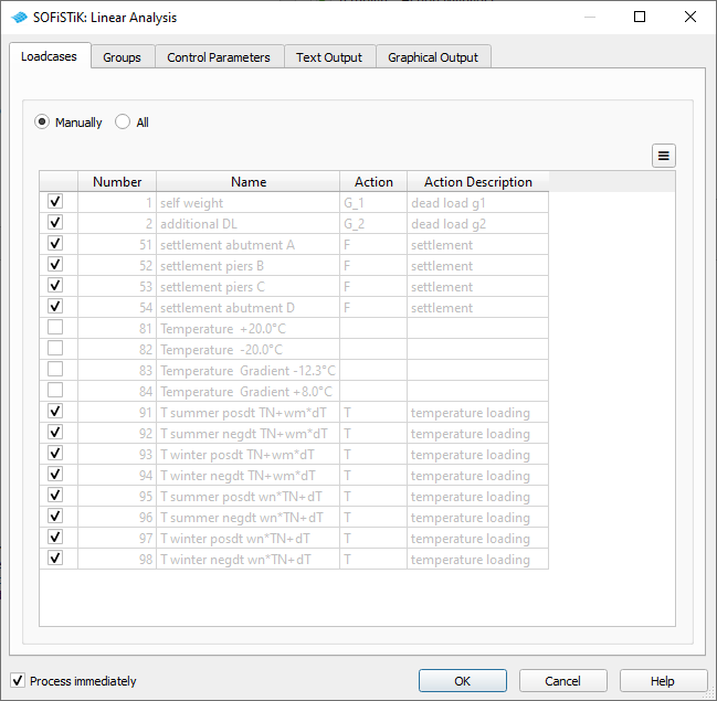
Linear Analysis
After all standard loads like self weight, temperature and settlement are defined we insert a new task “Linear Analysis”. Inside this task we change the load case selection from automatic to manual and select the loadcases 1,2,51,52,53,54 and 91 to 98.
Traffic Loads
In this tutorial we do not take into account the construction stages, but proceed directly with the traffic loads. Besides the general method with the influence line method we want to introduce a second method to apply the traffic loads on the bridge. This method is called the “Load Stepping Method”. This method is a very straight forward method with lot’s of single load cases, which will be analysed and superposed to get the envelopes for the further design tasks.
Load Case Numbering
Processing this method for the evaluation of traffic loads we need first a list of all necessary loadcases. We recommend the following numbering system:
LC |
Action |
Designation |
|---|---|---|
1201 |
NONE |
load train with load model LM1and 300 kN axle load |
1202 |
NONE |
load train with load model LM1and 200 kN axle load |
1203 |
NONE |
load train with load model LM1and 100 kN axle load |
201 - 225 |
NONE |
GR_T load stepping TS right most |
301 - 325 |
NONE |
GR_T load stepping TS left most |
401 - 425 |
NONE |
GR_T_T load stepping TS center |
501 - 503 |
NONE |
GR_U load stepping UDL right most; 3 spans |
521 - 523 |
NONE |
GR_U load stepping UDL left most; 3 spans |
541 - 543 |
NONE |
GR_U load stepping UDL center; 3 spans |
561 - 563 |
NONE |
GR_U footway and cycle track; 3 spans |
600 - 619 |
GR_T |
GR_T envelope GR_T |
620 - 639 |
NONE |
GR_U envelope GR_U right most + footways; 3 spans |
640 - 659 |
NONE |
GR_U envelope GR_U left most + footways; 3 spans |
660 - 679 |
NONE |
GR_U envelope GR_U center + footways; 3 spans |
680 - 699 |
GR_U |
GR_U envelope GR_U; 3 spans |
Workflow Load Stepping Method
The following steps are necessary to perform this analysis:
Define lanes within SOFiLOAD module. The correct input looks like:
+prog sofiload
head 'Lanes'
echo lane full
sto#start 10.00 $ station value bridge begin
$ For load stepping method together with SOFiLOAD COPY
$ it is necessary to define the bridge spans
$ this will be done with SA and SE input.
lane 'AXIS' type ec wr 6.10 wl -6.10 yra 6.9750  yla -6.9750 $$
      sa #start+0.00        se #start+16.20
      sa #start+16.20       se #start+16.20+19.60
      sa #start+16.20+19.60 se #start+16.20+19.60+16.20
end
2) Define load trains within SOFiLOAD module. The loads are saved in the following load cases:
+prog sofiload
head 'Load Models'
echo load yes
lc 1201 type none ; trai LM1 300  $ LM1 double axle load 300 kN
lc 1202 type none ; trai LM1 200  $ LM1 double axle load 200 kN
lc 1203 type none ; trai LM1 100  $ LM1 double axle load 100 kN
end
3) Generate a series of load cases for TS loads including different positions within the lanes (center, most right, most left):
+PROG SOFILOAD
HEAD 'LOAD STEPPING LM1 TS'

LC 201 TYPE NONE  TITL 'LM1:TS LANE 10/11/12 POS1'
COPY NO 1201 FACT 1.0 TYPE GR0 REF 'AXIS.10' DX 12.5

END
4) Generate a series of load cases for UDL loads including different positions within the lanes (center, most right, most left)
+PROG SOFILOAD
HEAD 'LOAD STEPPING LM1 TS'

LC 501 TYPE NONE  TITL 'LM1:UDL LANE 10/11/12/R SPAN1'
COPY NO 1201 FACT 1.0 TYPE GRU REF 'AXIS.10' DX 0 FROM 1 TO - INC 0

END
5) Perform a linear analysis of all single load cases. Instead of using the task “Linear Analysis” we will use a task “Text Editor (TEDDY)” including the load case number variables we defined before. This enables us to use this task without changes in additional project files.:
+PROG ASE $ Linear Analysis
HEAD 'Analysis of Traffic Loads
PAGE UNII 0
CTRL OPT SOLV VAL - $  Soluti
LC (#lc_min1 #lc_max1 1)
LC (#lc_min2 #lc_max2 1)
LC (#lc_min3 #lc_max3 1)

LC (#lc_minu1 #lc_maxu1 1)
LC (#lc_minu2 #lc_maxu2 1)
LC (#lc_minu3 #lc_maxu3 1)
LC (#lc_minur #lc_maxur 1)
END
6) Create combinations and superposition for the TS envelope. All Loadcases from 201 to 255, from 301 to 325 and from 401 to 425 are acting exclusively. The results will be saved inside the action GR_T for further access. The commands using a standard combination look like that:
comb 1 stan base 0 type GR_T
lc (201  225 1) type a1   $ a1 -> mutually exclusive
...
7) Create combinations and superposition for the UDL envelope. Before we generate the envelope from all the UDL loads we must create additional combinations for the three evaluation cases(most right, most left, center) + footway loads. From these results we evaluate the final envelope for UDL loads.
As an option you may delete all load cases you do not user later on in the analysis. This can be done within a task “Text Editor (TEDDY)” and the following input example:
+PROG ASE $ Linear Analysis
HEAD 'Delete unused LCs'
ECHO FULL NO
 LC (#lc_min1  #lc_max1 1)   type del
 LC (#lc_min2  #lc_max2 1)   type del
 LC (#lc_min3  #lc_max3 1)   type del
 LC (#lc_minu1  #lc_maxu1 1) type del
 LC (#lc_minu2  #lc_maxu2 1) type del
 LC (#lc_minu3  #lc_maxu3 1) type del
 LC (#lc_minur  #lc_maxur 1) type del
 LC (#lcu1  #lcu1+16 1)      type del
 LC (#lcu2  #lcu2+16 1)      type del
 LC (#lcu3  #lcu3+16 1)      type del
END
Combinations
As we are not using any construction stage, we cannot use the CSM-DESI functionality to generate all necessary combinations. Also, we do not have any post tensioned or composite sections in our structure, which need a combination in module MAXIMA and later on in module AQB. For the design of this bridge we simply need standard combinations which we will generate inside the module MAXIMA within a new task “Text Editor (TEDDY)”. A standard combination is defined by a combination number and type.
comb no 4 extr desi
act G_1
act G_2
act F
act T
act GR_T
act GR_U
Based on that combinations we generate the necessary results for all elements with the superposition command.
Note
All element results are saved in load cases as well. Please make sure that you do not use any load case number twice. This may overwrite existing results. These result load cases do not contain any loads but only the element results.
Design Area Elements
For the design of area elements several steps must be followed
define design parameters for area elements
ULS design check
SLS - crack width design check
SLS - stress limitation check for concrete and reinforcement steel
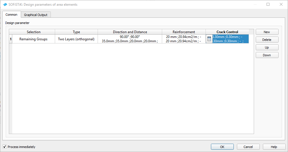
Design Parameters
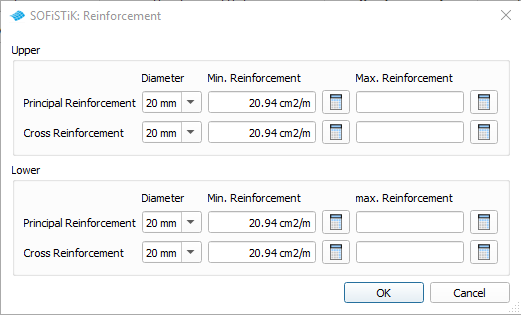
First of all you must define the design parameters of the area elements. These are reinforcement directions, distances, diameters and allowable crack width. To do that simply use the task “Design Parameter Area Elements”.
Note
The main reinforcement, which by definition is the outer reinforcement, is always facing in the same direction as the local x-axes of the QUAD elements. For a standard slab bridge the outer reinforcement direction is usually provided transversely to the sides of the bridge, which is usually the local y-axes. Therefore please set an angle of 90° for the upper and lower principal reinforcement. (see the following picture)
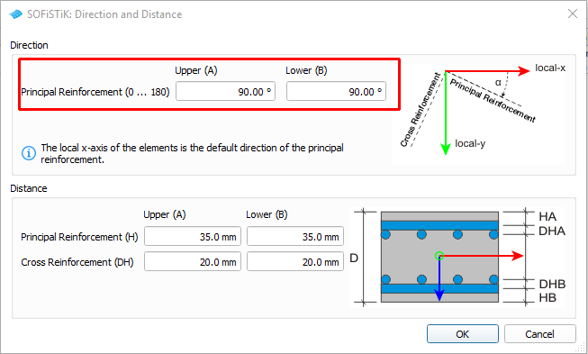
Diameter and reinforcement area will be defined in the tab “Reinforcement”
ULS Design
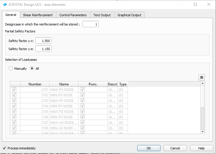
Doing the ULS design for area elements we follow the SSD task “Design ULS - area elements”. Simply add this task to your project and make necessary adjustments inside the dialogue.
For the connection from pier to the cross beams we do have to check punching. As the area thickness is different from the cross beams to the normal slab, you must do some manual checks. Nevertheless there is an option to check punching without changing the longitudinal reinforcement. This option will be used here.
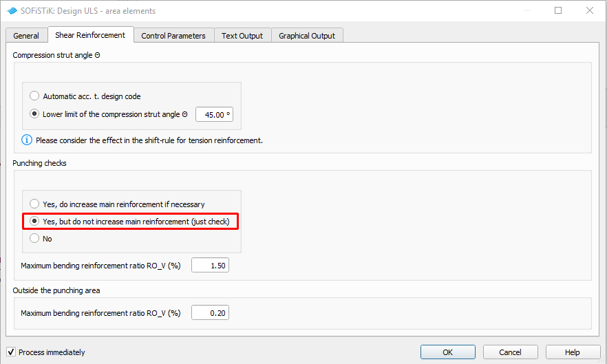
Inside the output you will find now a table with the design punching forces at each node for further design checks.
SLS Design - Crack Width Check
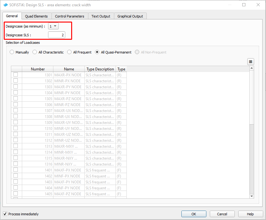
For the crack design check we will use again a standard SSD task”Design SLS - area elements”. Simply make all necessary adjustments inside this task.
SLS Design - Stress Limit Check
As the standard task does not check any stress limitations, we need to add a new task “Text Editor (TEDDY)” to our project. Do so and open the task to insert the following commands:
PROG BEMESS $ Stress Check for Characteristic Combination
HEAD Check concrete stress < 0.6 fck for characteristic combination
HEAD Check steel stresses  < 0.8 fyk for characteristic combination
PAGE UNII 0  ! standard input units

ECHO REIN,RSUG,RTAB,sigs yes
$echo full extr
CTRL TENS 0 $ no reduct. of concrete strength for cross-tension
CTRL PFAI 2 $ allowance for compression reinforcement

CTRL LCRI 2 $ Reinforcement distribution number as minimum
CTRL  LCR 3 $ Reinforcement distribution number to store the results

CTRL SLS
LC rare
NSTR CHKC 0.6 CHKS 0.8 $ Control of concrete compressive stress and steel stress

END

PROG BEMESS $ Stress Check for Permanent Combination
HEAD Check concrete stress < 0.45 fck for permanent combination
PAGE UNII 0  ! standard input units

ECHO REIN,RSUG,RTAB,sigs yes
CTRL TENS 0 $ no reduct. of concrete strength for cross-tension
CTRL PFAI 2 $ allowance for compression reinforcement

CTRL LCRI 3 $ Reinforcement distribution number as minimum
CTRL  LCR 4 $ Reinforcement distribution number to store the results

CTRL SLS
LC perm

NSTR CHKC 0.45   $ Control of concrete compressive stress

END
Envelope of Area Reinforcement
Finally we may combine all area reinforcement results from different design checks. This will be done manually again inside a SSD task “Text Input (TEDDY)”:
+PROG BEMESS
HEAD Maximum of the required reinforcement
$ Any LCR can be applied in order to create a maximum:
CTRL LCRI 1,2,3,4
CTRL LCR  10    $ writes the maximum of the reinforcement to LCR 10
END
Design Beam Elements
For the design checks of the beam elements we also use the standard SSD tasks as well as some user tasks “Text Input (TEDDY)” and work through the following steps:
ULS design check
SLS - crack width design check
SLS - stress limitation check for concrete and reinforcement steel
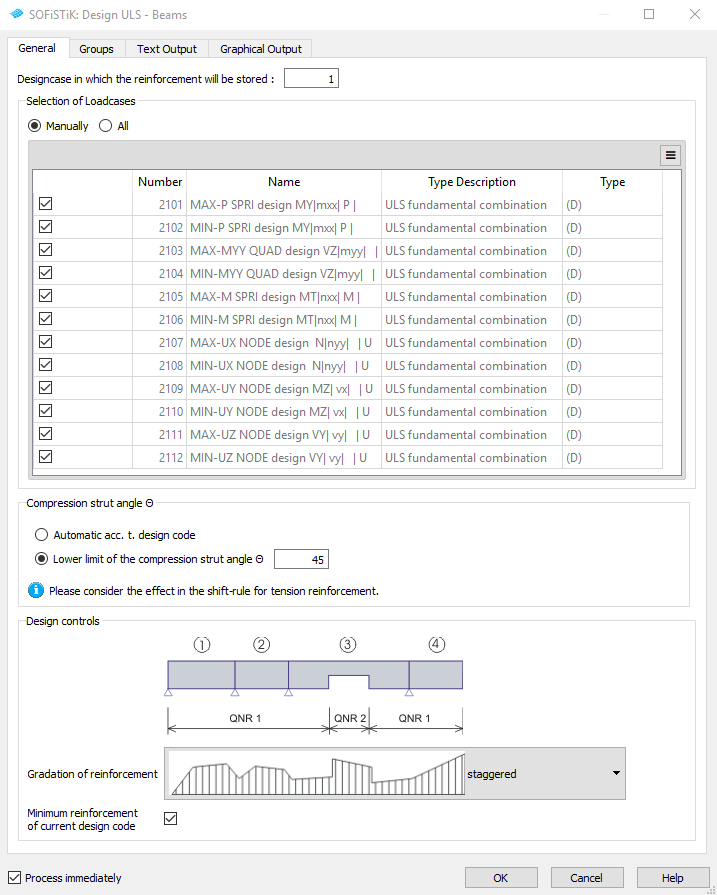
ULS Design
Doing the ULS design for beam elements we follow the SSD task “Design ULS - Beams”. Simply add this task to your project and make necessary adjustments inside the dialogue.
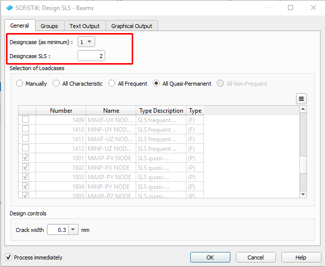
SLS Design - Crack Width Check
For the crack design check we will use again a standard SSD task “Design SLS - Beams”. Simply make all necessary adjustments inside this task.
SLS Design - Stress Limit Check
As the standard task does not check any stress limitations, we need to add a new task “Text Editor (TEDDY)” to our project. We need to create a standard AQB design input with selection of loadcases, definition of beam elements, definition of design combinations. In our case we split up the design checks for concrete and for reinforcement steel. The commands for the design checks are:
NSTR CHKC -0.6 KSV SL $ check concrete stress nonlinear <0.6 fck

NSTR CHKS 0.80 KSV SL $ = steel stress < 0.80 fyk
Documentation
For the final documentation, you can collect all single reports and generate a complete document. Please follow the explanations of chapter Generate Report from the General Workflow description.


