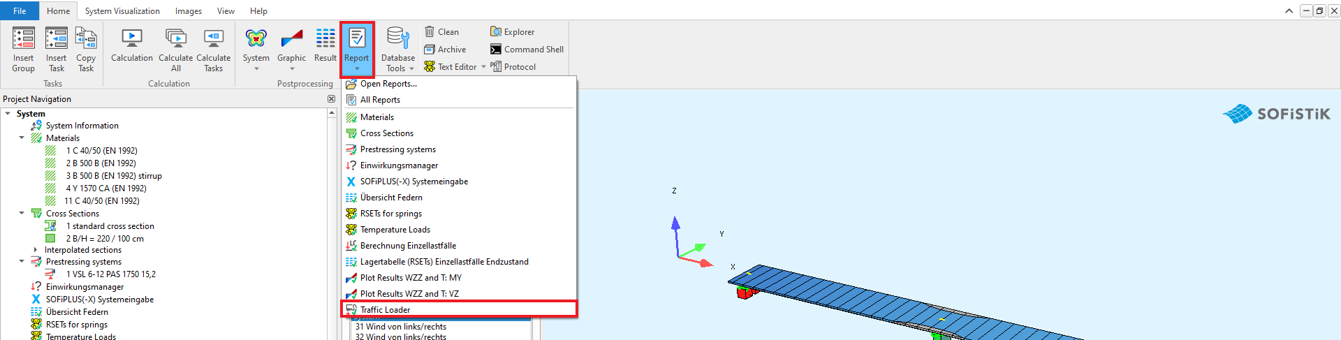
Traffic Loader
Important
This section describes the general settings of the Traffic Loader Task. It contains explanations of the corresponding dialog options, grouped by tab. The CADINP input per dialog is shown as example. This is a supplement to the tutorials. It does not contain step-by-step instructions for applying traffic loads according to the concept of influence lines.
Overview
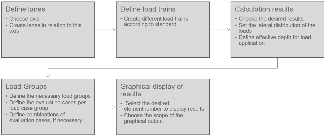
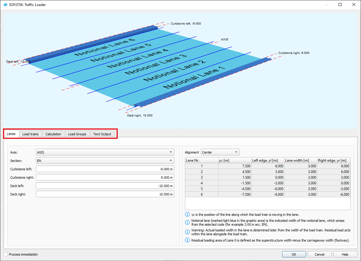
Lanes
Inside the dialogue there are 5 tabs. The first tab - Lanes - you define the lanes, where the traffic passes over your bridge.
+PROG SOFILOAD $ Traffic Loader
HEAD POSITIONAL VARIANTS OF LOAD TRAINS
PAGE UNII 0

LANE AXIS TYPE EN WL -9 WR 9 YLA -10 YRA 10
ECHO LANE FULL
...
END
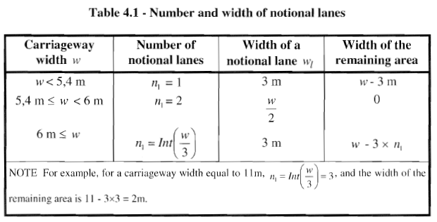
Eurocode EN 1992-2 Table 4.1 Number of notional lanes
By selecting the standard cross-section “EN” the rules of table 4.1 are applied.
Depending on the dimensions, several lane orientations are generated: “centered”, “right”, “left” and “superstructure width”
The idea behind it: The resulting lane orientations are used to load the bridge unfavorably.
Ultimately, the user has to decide for himself, which lanes/notional lanes have to be loaded with which load trains.
If necessary, lanes/notional lanes can be created manually.
Note
EN 1991-2 Chapter 4.2.4(2): (2) For each individual verification (e.g. for a verification of the ultimate limit state of resistance of a cross-section to bending), the number of lanes to be taken into account as loaded, their location on the carriageway and their numbering should be so chosen that the effects from the load models are the most adverse.
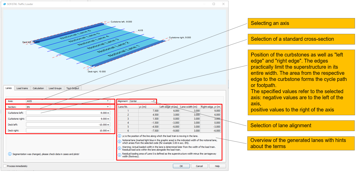
Definition of the terms ‘lane’, ‘notional lane’ and ‘residual area’
A ” lane ” contains a left and right edge and a line yc, which does not have to be located centrally between the edges. The vehicle moves along the line yc. Loads always act only within the loaded lane, loads outside the lane are “clipped”, i.e. simply ignored.
A “notional lane” results only through the load train, which is applied in a lane: the load train LM1 has a defined width of 3.00 m; if this is applied in one lane, the “notional lane” results to exactly this width, i.e. 3.00 m; this notional lane is centered on the line yc within the lane.
A “residual area” is always within the loaded lane next to the vehicle: If a lane has a width of 4.00 m and an LM1 is placed on this lane, a “residual area” of 0.50 m width results to the right and left of the LM1 (of the notional lane) when yc is positioned centrally.
Alignment
The following lane orientations are automatically generated when selecting stand cross-section “EN”.
Note
If there is exactly space between the curbstones for 1,2,3,4,5 or 6 lanes (i.e. 3.00 m, 6.00 m, … 18.00 m), a lane orientation is generated “centered”: Lanes 1 to 6 are arranged side by side from right to left, all of them have a width of 3.00 m. In the graphic, the “notional lanes” that would result with a 3.00 m wide vehicle within the lane are highlighted in light blue.
The following lane orientations are automatically generated when selecting stand cross-section “EN”.
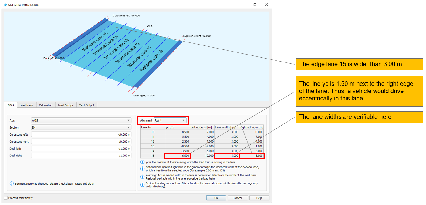
From more than approx. 20.00 m between the curbstones, a lane alignment is also generated “centered”. Again, all lanes from 1 to x are numbered from right to left, but these are arranged in the middle between the curbstones. All lanes in the middle have a width of 3.00 m, only the two edge lanes reach to the curbstones and have a larger width. In these wider lanes, the “notional lane” is again indicated in light blue, which would result in a 3.00 m wide vehicle.
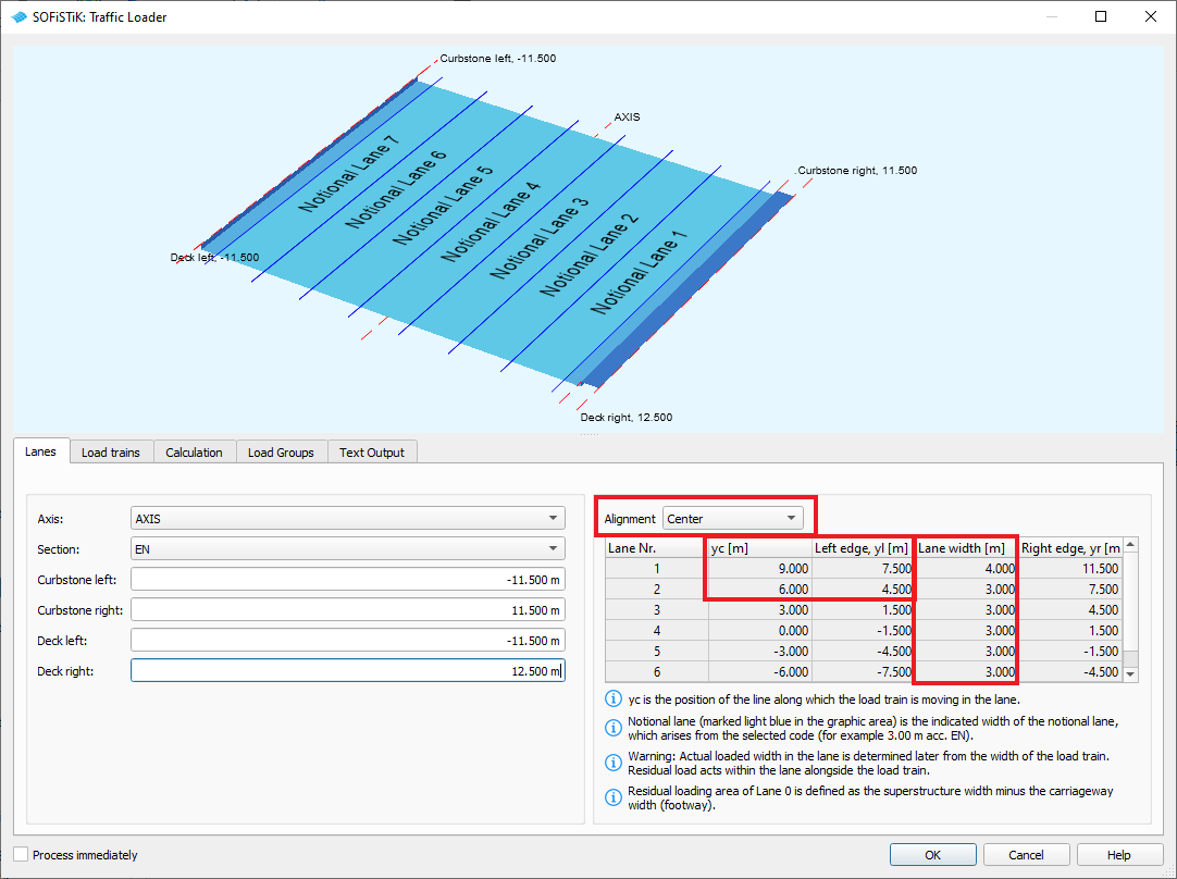
Edge lanes 1 and 7 are wider than 3.00 m
The line yc is, for example, for lane 1 1.50 m next to the left edge of the lane. Thus, a vehicle would drive eccentrically in this lane.
The lane widths are verifiable in the lane table
The following lane orientations are automatically generated when selecting standard cross-section “EN“:
If there is a width between the curbstones unequal to an integer multiple of 3.00 (and up to a maximum of about 20.00 m), the lane alignments are generated “centered”, “right” and “left”.
At the alignment “centered” the lane 1 is in the middle, then alternately follow right, left, right, left lanes 2, 3, 4 and 5 (up to a maximum of 5 lanes). The middle lanes have a width of 3.00 m each, only the edge lanes reach with an edge to the curbstone and are therefore wider.
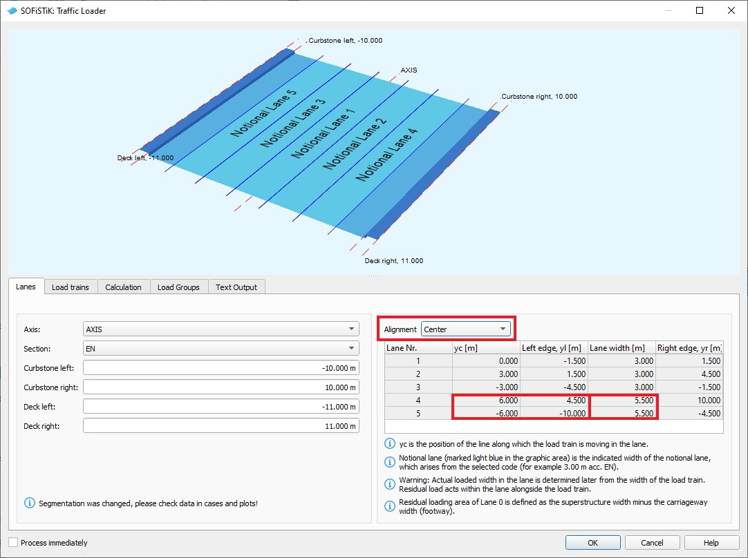
Edge lanes 4 and 5 are wider than 3.00m
The line yc is, for example, for lane 4 1.50m next to the lane. Thus, a vehicle would drive eccentrically in this lane.
The lane widths are verifiable in the lane table
The following lane orientations are automatically generated when selecting standard cross-section “EN“:
With the “right” alignment, lane 10 is right-aligned on the curbstone, lanes 11 to a maximum of 15 follow on the left.
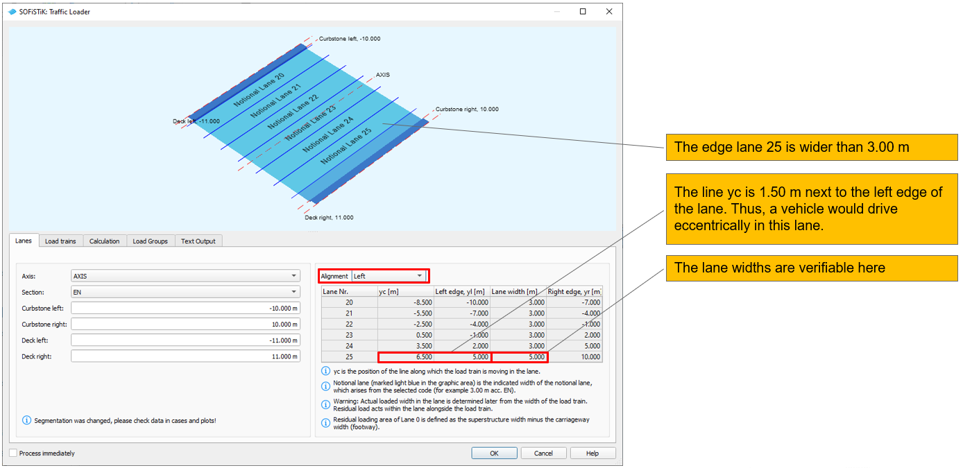
The following lane orientations are automatically generated when selecting standard cross-section “EN“:
With the “left” alignment, lane 20 is left-aligned on the curbstone, followed by tracks 21 to a maximum of 25 on the right.
The following lane alignments are generated automatically:
In addition, a lane “0” is defined in all cases. This is the “overall width”, i.e. the width between the curbstones plus the width of the cycle path or footpath and is referred to, as the “superstructure width”. In order to load the cycle/footpath, the remaining areas of lane “0” are addressed.
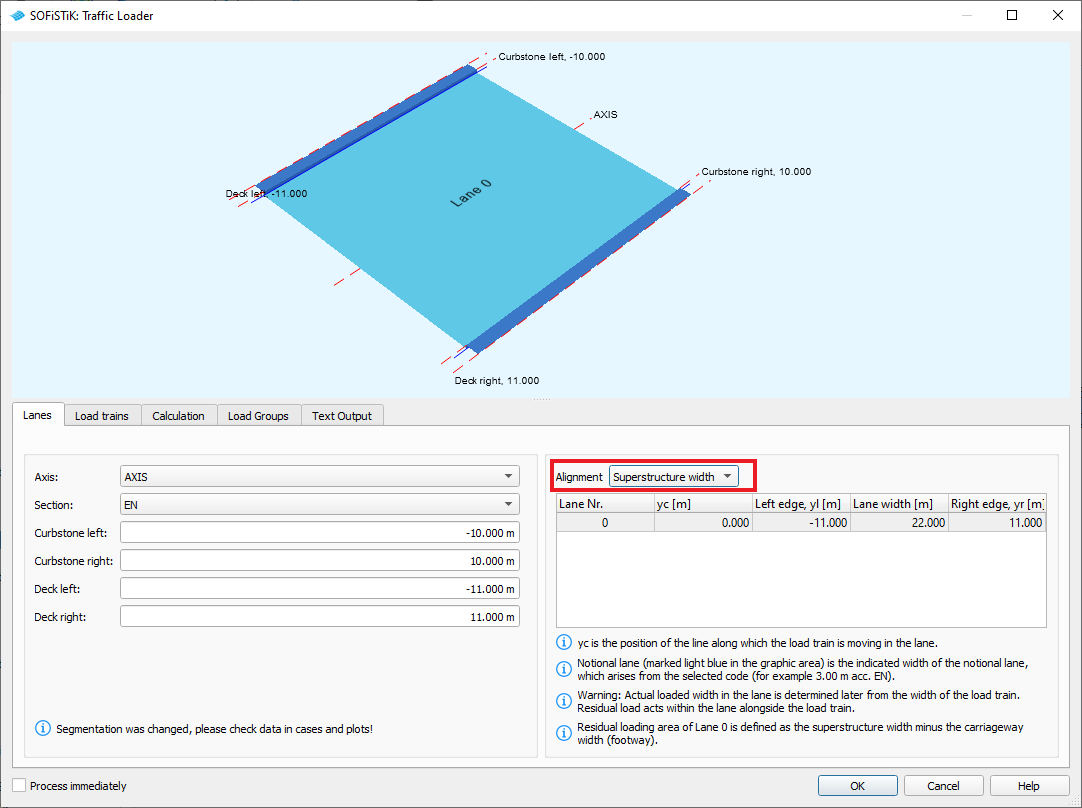
Lane 0 => Superstructure.
The residual areas of lane 0 are the cyle/footpaths.
Residual Area
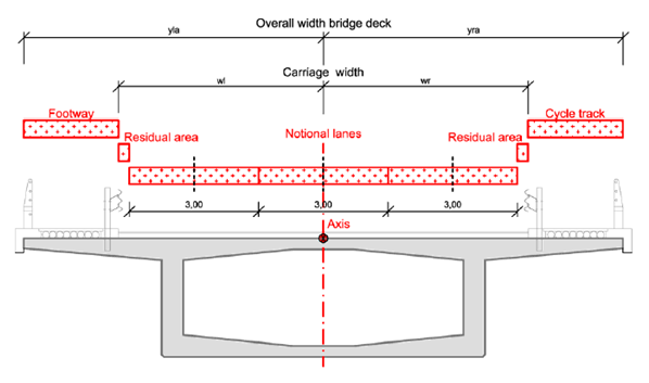
Distribution of lanes in the bridge cross-section - residual area
Important
Residual areas are always part of a lane! This means that the edge lanes in the image have a widt of 3.00m + width of the residual area, see also below!
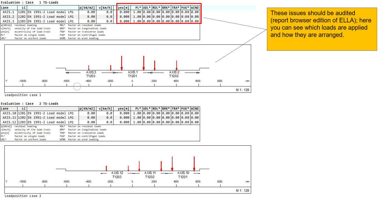
Results
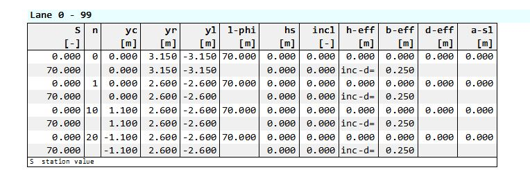
In the Report of PROG SOFiLOAD, from task Traffic Loader, you will find informations about lane geometry (ECHO LANE FULL).
Important
These should always be checked!
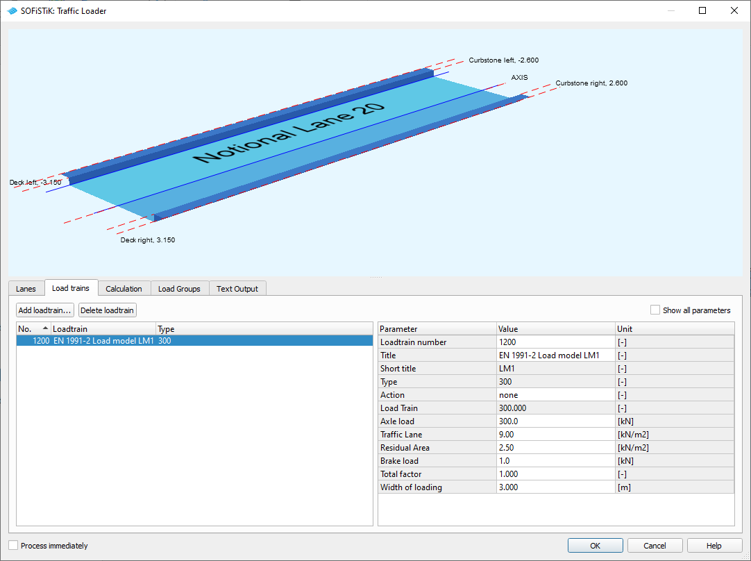
Load Trains
+PROG SOFILOAD $ Traffic Loader
HEAD POSITIONAL VARIANTS OF LOAD TRAINS
PAGE UNII 0

LANE AXIS TYPE EN WL -2.6 WR 2.6 YLA -3.15 YRA 3.15

ECHO LANE FULL

$ Input Load Trains
LC NO 1200 TYPE none TITL 'EN 1991-2 Load model LM1'
TRAI LM1 P1 300 P2 300 P4 9 P5 2.5 P8 1 PFAC 1 WIDT 3
$ Input Load Trains
END
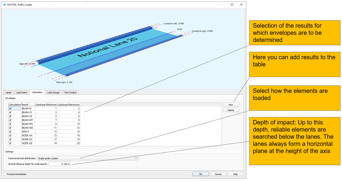
Calculation
Important
in the dialog, no evaluation of the RSETs can be selected yet!
This has to be done manually at the moment. Recommended workflow:
Make all necessary and possible settings in the dialog, disable the option “Run Immediately” at the bottom left and exit the dialog with “OK”. Then copy the task, convert it to a text task and manually add required lines regarding the RSETs (see the following pages). Then open the original task with the teddy and deactivate the modules -> this ensures that when the complete task tree is recalculated, only the manually adapted task is calculated.
+PROG ELLA urs:32.1 $ Traffic Loader
HEAD AUTOMATIC EVALUATION OF LOAD TRAINS
PAGE UNII 0
SIZE URS 0 HDIV 3 $ 0.30
ECHO OPT LPOS VAL FULL $ Load position
SHOW SNO AXIS TYPE BEAM NO 200010 ETYP EXTR
$Input Calculation Tab
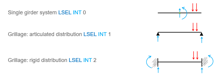
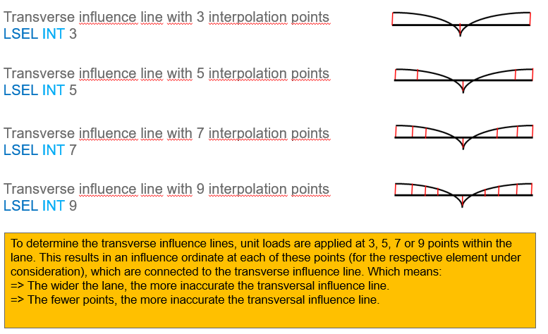
LSEL AXIS INT 0 DZ 0.1 $ RSEL GRP 0
CALC N LMAX 2 LMIN 1
CALC VY LMAX 4 LMIN 3
CALC VZ LMAX 6 LMIN 5
CALC MT LMAX 8 LMIN 7
CALC MY LMAX 10 LMIN 9
CALC MZ LMAX 12 LMIN 11
CALC P LMAX 14 LMIN 13
CALC UX LMAX 16 LMIN 15
CALC UY LMAX 18 LMIN 17
CALC UZ LMAX 20 LMIN 19
APPL FULL
$Input Calculation Tab
...
Distribution of loads - Beam systems
Distribution of loads - Area elements
Necessary addition for RSETs
In PROG ELLA, a superposition of the RSET values must now also be requested
In the CALC command, the input RSET:…
The input CALC RSET:PX requests the determination of the maximum RSET size ‘PX’ (again analogue to the input CALC MY, which requests the determination of the maximum beam force MY)
Just as CALC MY treats all beams, that have the internal forces MY, CALC RSET:PX treats all RSETs that contain this RSET value
For the RSETs a reasonable numbering LMAX and LMIN must be selected
 +PROG ELLA urs:32.1 $ Traffic Loads
HEAD AUTOMATIC EVALUATION OF LOAD TRAINS
PAGE UNII 0

 SIZE URS 0 HDIV 3 $ 0.30

 SHOW SNO AXIS TYPE BEAM NO 200010 ETYP EXTR

 LSEL AXIS INT 0 DZ 0.1 $ RSEL GRP 0
 CALC N LMAX 2 LMIN 1
 CALC VY LMAX 4 LMIN 3
 CALC VZ LMAX 6 LMIN 5
 CALC MT LMAX 8 LMIN 7
 CALC MY LMAX 10 LMIN 9
 CALC MZ LMAX 12 LMIN 11
 CALC P LMAX 14 LMIN 13
 CALC UX LMAX 16 LMIN 15
 CALC UY LMAX 18 LMIN 17
 CALC UZ LMAX 20 LMIN 19

 $ addition for RSETs
 let#start 21
 CALC RSET:PX LMAX #start+1 LMIN #start
 CALC RSET:PY LMAX #start+3 LMIN #start+2
 CALC RSET:PZ LMAX #start+5 LMIN #start+4
 CALC RSET:VX LMAX #start+7 LMIN #start+6
 CALC RSET:VY LMAX #start+9 LMIN #start+8
 CALC RSET:VZ LMAX #start+11 LMIN #start+10
 CALC RSET:PHIX LMAX #start+13 LMIN #start+12
 CALC RSET:PHIY LMAX #start+15 LMIN #start+14
 CALC RSET:PHIZ LMAX #start+17 LMIN #start+16
 $ addition for RSETs
 APPL FULL
Load Groups
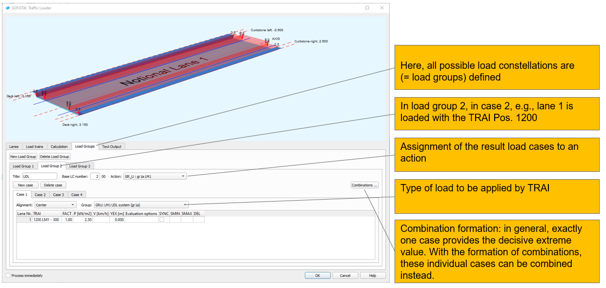
+PROG ELLA urs:32.1 $ Traffic Loader
HEAD AUTOMATIC EVALUATION OF LOAD TRAINS
...
SAVE LCB 100 TYPE GR_T TITL 'TS'
CASE 1 GRP GR0
POSL AXIS.1 TRAI 1200 FACT 1 YEX 0 P 2.5 SYNC OFF PLON VAR PTRA VAR FUGA CODE IMPA ON EXCE FIX EXTR ALL OPT FREE
CASE 2 GRP GR0
POSL AXIS.1 TRAI 1200 FACT 1 YEX 0 P 2.5 SYNC OFF PLON VAR PTRA VAR FUGA CODE IMPA ON EXCE FIX EXTR ALL OPT FREE
CASE 3 GRP GR0
POSL AXIS.1 TRAI 1200 FACT 1 YEX 0 P 2.5 SYNC OFF PLON VAR PTRA VAR FUGA CODE IMPA ON EXCE FIX EXTR ALL OPT FREE

SAVE LCB 200 TYPE GR_U TITL 'UDL'
CASE 1 GRP GRU
POSL AXIS.1 TRAI 1200 FACT 1 YEX 0 P 2.5 SYNC OFF PLON VAR PTRA VAR FUGA CODE IMPA ON EXCE FIX EXTR ALL OPT FREE
CASE 2 GRP GRU
POSL AXIS.1 TRAI 1200 FACT 1 YEX 0 P 2.5 SYNC OFF PLON VAR PTRA VAR FUGA CODE IMPA ON EXCE FIX EXTR ALL OPT FREE
CASE 3 GRP GRU
POSL AXIS.1 TRAI 1200 FACT 1 YEX 0 P 2.5 SYNC OFF PLON VAR PTRA VAR FUGA CODE IMPA ON EXCE FIX EXTR ALL OPT FREE
CASE 4 GRP GR3
POSL AXIS.0 P 2.5

COMB A0 1 1.0 4 1.0
     A0 2 1.0 4 1.0
     A0 3 1.0 4 1.0
Note
Categories to map load groups: By defining the parameter ACT… PART Q_1, Q_2, Q_3 … these effects are treated in the same way as the load groups in Table 4.4a: only load cases of either group Q_1 or Q_2 or Q_3 … A call in the PROG MAXIMA with ACT GR _ … automatically considers these categories of action GR with correct psi values. MAXiMA also knows, that the categories GR_T and GR_U can act simultaneously, since both were defined as PART Q_1
+PROG SOFiLOAD
HEAD 'ACTIONS'

ACT 'GR_T' GAMU 1.35 0.00 PSI0 0.75 0.00 PART Q_1 SUP EXCL TITL "gr1a TS"
ACT 'GR_U' GAMU 1.35 0.00 PSI0 0.40 0.40 PART Q_1 SUP EXCL TITL "gr1a UDL"
ACT 'GR_2' GAMU 1.35 0.00 PSI0 0.00 0.00 PART Q_2 SUP EXEX TITL "gr2 Horizontal Forces"
ACT 'GR_3' GAMU 1.35 0.00 PSI0 0.00 0.00 PART Q_3 SUP EXEX TITL "gr3 Footways"
ACT 'GR_4' GAMU 1.35 0.00 PSI0 0.75 0.75 PART Q_4 SUP EXEX TITL "gr4 crowd load"
ACT 'GR_5' GAMU 1.35 0.00 PSI0 0.00 0.00 PART Q_5 SUP EXEX TITL "gr5 LM3 freq LM1"

END
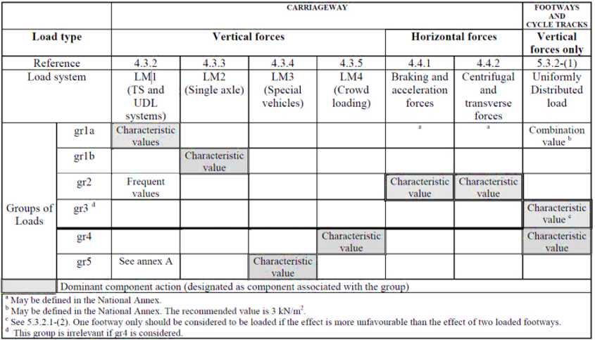
Table EN 1991-2- Table 4.4a - Groups of traffic loads
Text Output
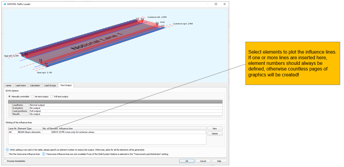
+PROG ELLA urs:32.1 $ Traffic Loader
HEAD AUTOMATIC EVALUATION OF LOAD TRAINS
PAGE UNII 0

SIZE URS 0 HDIV 3 $ 0.30

ECHO OPT LOAD VAL YES $ Loadtrains
ECHO OPT EVAL VAL NO $ Evaluation
ECHO OPT LPOS VAL FULL $ Load positions
ECHO OPT RES VAL NO $ Results

SHOW SNO AXIS TYPE BEAM NO 200010 ETYP EXTR
...