Steel - buckling resistance of members
The task Buckling Resistance of Members contains:
Design Code tab
Loadcases tab
Selection tab
Text Output tab
Tip
If you click on the figure it will show up in original size.
See also
The task “Buckling Resistance of Members” was explained in the Portal Frame tutorial (Analysis and Design).
Design Code tab
The Design Code tab is the first step, where the design code should be selected. In version 2018, following design codes are available:
Eurocode 3
DIN 18800 / OEN 4300
Hint
In version 2020, the design code BS 5950 has been removed from the BDK task in SSD. The design code is not maintained any more.
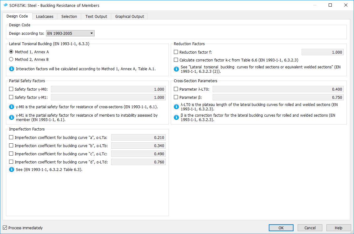
Depending on the selected design code, the task will show up corresponding options. For e.g. Eurocode 3 you can select between method 1 and 2, you can modify the partial safety factors, change the imperfection factors for the buckling curves, change the cross-section parameters etc.
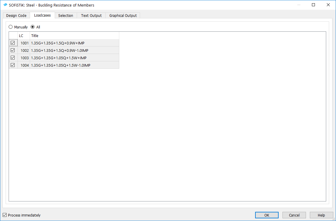
Loadcases tab
The Loadcases tab will show all loadcases with an action “Design (D)”. Next steps are necessary to define a “Design (D)” loadcase:
Run the defined loadcases with the “Linear analysis” task
Combine the loads with the “Combine Loads” task, there you should select the type of the results “ULS - combination”
Analyze the combined loadcases with the task “Analysis of Combined loadcases”
Selection tab
The Selection tab is the most important tab in the task. It contains two tables:
Structural lines
Sequence of Structural lines
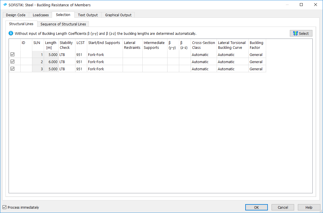
The table for Structural lines shows all available structural lines with steel material. The table for Sequence of Structural lines is used to generate a sequence of the existing structural lines.
E.g. you can convert two or more structural lines to one design element.
Hint
The requirements for create a sequence of structural lines are:
the structural lines are connected,
the new design element (structural lines sequence) should be straight.
If this conditions are NOT met, then you will get a warning in BDK.
In the table bellow you will find the description for “Structural lines” and “Sequence of Structural lines” table columns.
Column |
Description |
|---|---|
ID |
Identification number of the design element. If nothing is specified BDK will try to use “SLN Number” = “ID Design Element Number”. |
SLN |
Identification number of the structural line |
Sequence |
Sequence of structural lines. In the “Sequence of structural lines” column, you can need to define more than one SLN (“,” character is the separator, “-” will take into account all loadcase number “from - to”). Bellow you will find few input examples. If you want to create a sequence of structural lines 1 and 2: 1,2
If you want to create a sequence of structural lines 1, 2, 10, 11 and 12: 1,2,10-12
etc. It is highly recommended that you always define a custom design element number for “Sequence of structural lines” (ID). (e.g. 1001) |
Length |
Length of the structural lines |
Stability Check |
Stability check is the type of the buckling check. There are 3 available options:
DIN 18800/OEN 4300
BS 5950
|
LCST |
Loadcase number for storing the results In the LCST column, you can add more than one LCST value (“,” character is the separator, “-” will take into account all loadcase number “from - to”). Bellow you will find few input examples. To save the results to loadcase 951 input: 951
To save the results to loadcases 951 and 953 input: 951,953
The results will be saved to loadcases 951, 952, 955, 956, 957, 958: 951,952,955-958
etc. |
Start/End Supports |
The boundary conditions for START and END of the design element are here explicit defined. Default is “Fork-Fork”. |
CVL (Lateral Restraints) |
The lateral restraints (Continuous and Point) along the design-element are defined in this column.
|
CVM (Intermediate Supports) |
Define intermediate supports at position of Structural Points. The table will show all structural points along the design element. For Intermediate Supports you can define CB, CY, CZ, DX, DY, DZ boundary conditions (see BDK Manual for more details). |
β (y-y) and β (z-z) |
Buckling factors. If nothing is specified the buckling lengths will be determined automatically (default). |
Cross-Section Class |
If automatic is defined then the cross-section class will be determined automatically. It is also possible to input the cross-section class manually. |
Lateral Torsional Buckling curves |
If automatic is defined then the buckling curves will be determined automatically. It is also possible to input the LTB buckling curves (a,b,c,d) manually. |
Buckling Factor |
Two options are possible (Eurocode 3 only):
|
Sway (y-y), Sway (z-z) |
If the sway checkboxes is checked, BDK will set the equivalent uniform moments Cmy = 0.90 or Cmz = 0.90 respectively (EN 1993-1-1, Method 2, Table B.3.). If the sway mode is un-checked, then BDK will determine the Cmy and Cmz values according to the Eurocode formulas. |
Torsional susceptible |
If automatic is selected BDK will try to find automatically if the cross-section is torsional susceptible. The type of the cross-section is checked. Also the moment of inertia It is compared with Iy and Iz. If you want to modify this value explicitly, then Yes or No options are available (acc. to EN 1993-1-1, Method 2 (Annex B), Table B.1 or B.2) |


