Slab Design
The Slab Design dialog allows to perform a check or design of the required reinforcement for selected slab members which are in the same level plane.
Click .
Select one or multiple slab members at the same level.
In the design dialog which opens, insert a name for the ‘’Design Group’’.
Check and adjust settings.
Click OK to close and save the settings or click Calculate to perform the design calculation.
Important
Slab designs can only be performed if the system used as data source has been generated and its load cases calculated.
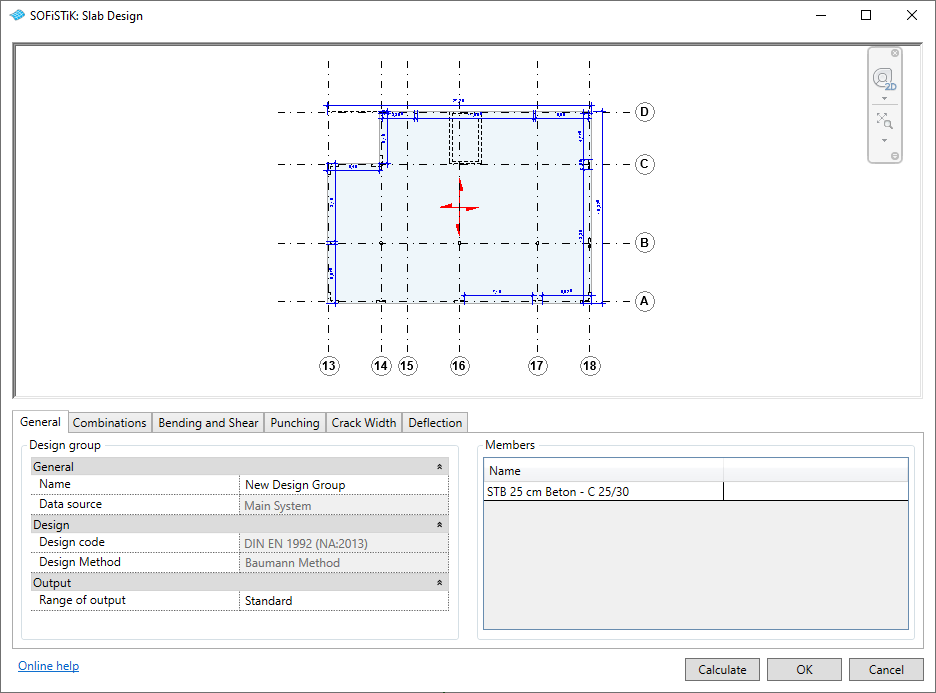
The design configuration dialog shown above contains a 2D overview of the selected slabs and the following tabs:
When successfully closing the dialog, the selected slabs will be assigned to a so-called ‘’Design Group’’ allowing to identify the set of slabs for later readjustment and recalculation. Design groups are organized in the SOFiSTiK Design Browser. There, the stored design configuration can be opened again for modification or completion of the analysis. It also allows to change the data source for the design groups, to start the design calculation or to access design reports.
When closing the dialog by clicking Calculate, the SOFiSTiK Analysis Task Monitor appears and the design calculation is performed. After successful completion of the calculation, the design report can be opened.
Note
In case the SOFiSTiK Design Browser is not visible, it can be opened through the menu via .
General
Provides general information including the Design Group name.
Note
Design Group name and Data source can only be modified via the SOFiSTiK Design Browser from outside the dialog.
Combinations
Allows you to select the load combination types used in the following designs. Options are:
Automatic combinations (recommended)
Analysis results of individual load cases will be combined for each Finite Element using SOFiSTiK MAXiMA, following the combination rule of Eurocode EN1990. Resulting forces and stresses represent envelops, not a singular load combination, for each Finite Element and will be used for the design.
for the Ultimate Limit State according to Eq. (6.10) fundamental
for the Serviceability Limit State according to Eq. (6.14b) characteristic (rare) or Eq. (6.15b) frequent or Eq. (6.16b) quasi permanent
The resulting load combination is defined by a combination of the load combination type and the calculated internal force. The following table gives an overview of the generation. As an example:
The envelop of the support reaction PZ,max for ULS fundamental, which is used for punching design, will be LC 2155.
Load combination typeNumber( X X _ _ )Internal forces (max/min)Number (max/min)( _ _ Y Y / Z Z)ULS fundamental
2 1 _ _
Bending moment mxx
_ _ 0 1 / 0 2
SLS characteristic (rare)
1 1 _ _
Bending moment myy
_ _ 0 3 / 0 4
SLS non-frequent
1 2 _ _
Torsional moment mxy
_ _ 0 5 / 0 6
SLS frequent
1 3 _ _
Shear force vx
_ _ 0 7 / 0 8
SLS quasi permanent
1 4 _ _
Shear force vy
_ _ 0 9 / 1 0
Normal force nxx
_ _ 1 1 / 1 2
Normal force nyy
_ _ 1 3 / 1 4
Support reaction PZ
_ _ 5 5 / 5 6
Nodal displacement UZ
_ _ 7 5 / 7 6
For further information, please consult the SOFiSTiK MAXiMA manual.
Globally defined load combinations
Revit load combinations are available throughout all analysis and design task. To learn more, see SOFiSTiK Load Combinations tool.
For the globally defined load combinations, individual combinations may be (de-)selected.
Note
The selection of load combinations must match the Load combination type choice in the following tabs.
Bending and Shear
Allows to set reinforcement boundary offset and the compression strut angle.
Hint
The major direction for the reinforcement settings is the span direction of slab. The minor direction for the reinforcement settings is always orthogonal to the major direction.
Punching
Allows to set the punching design mode to Punching design or Punching check only, the latter performing a tabular check according to Eurocode without increasing the required reinforcement.
Crack Width
Allows to set crack width design mode, permitted crack width and reinforcement settings.
Deflection
Allows to set parameters for a linear deflection check based on the selected load combinations type.
Note
Deflection threshold determines value of deflection which will be indicated in the report. It does not affect the design.
For slab design, the following design cases will be used:
Design Case |
Description |
|---|---|
1: ULS Design
|
required reinforcement for ULS design only
(individually for each item of design group)
|
2: ULS + SLS Design
(envelop)
|
required reinforcement for ULS + SLS design
(envelop of both design cases)
|
See also
Find out more about globally defined load combinations.


