Settings Dialog
In Settings Dialog you can define user specific settings, such as File Locations for Revit Families or project accuracy.
Click SOFiSTiK Bridge tab
 Create panel Create drop-down
  (Settings)
SOFiSTiK: Settings window displays.
Adjust settings according to your wish and confirm with OK.
General
You can define below listed settings to define the behaviour of your model.
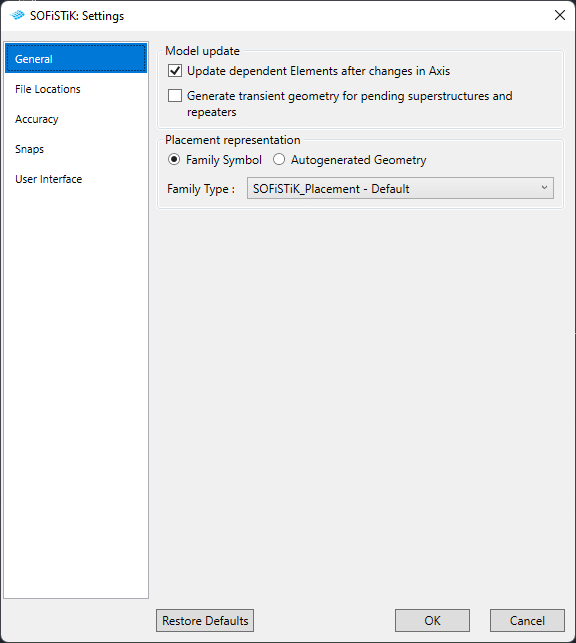
Model Update
You can decide whether dependent elements of the axis should be automatically updated or not.
Transcient Geometry
You can decide whether or not create transcient geometry for the definition of Pending Definition of Superstructure and Repeaters. Transcient Geometry are very fast to create, but appear only in the current Revit session.
File Location
You can define the location of family templates and Revit Families
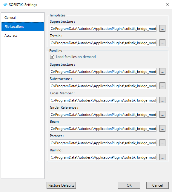
Templates
Select directory to the Family Templates, that will be used to create following elements:
Superstructure Component
Terrain Model
Families
Select directory to the folders from which the families will be loaded while starting following commands:
‘Load Families on demand’ checkbox - if deactivated, families will not be loaded while starting the command.
Superstructure
Substructure
Cross Member
Girder Reference (Girder Layout command)
Beam
Parapet
Railing
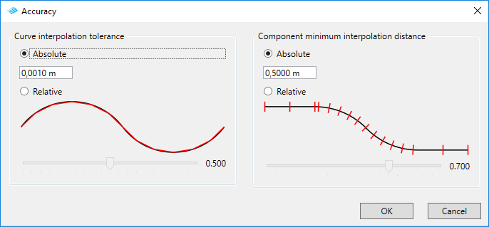
Accuracy
You can set the accuracy of your superstructure components.
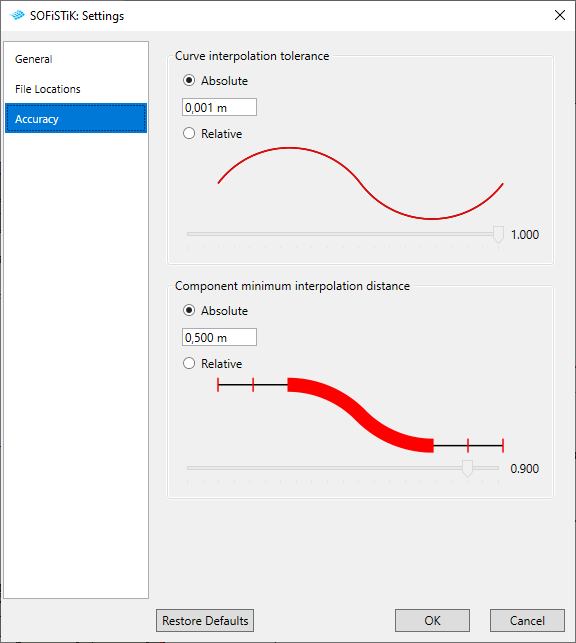
Curve interpolation tolerance
Absolute - maximum tolerance of deviation of interpolated axis. Created curve is used as a path for profiles in superstructure components family.
Relative - factor relative to the axis length between minimum and maximum deviation tolerance of interpolated axis.
Interpolated Axis is used as a path for profiles in superstructure component family.
Note
Given ‘Absolute’ value is also used as a accuracy control of the imported axis from LandXML file format.
Component minimum interpolation distance
Absolute - minimum distance between two profiles of created superstructure component. Each component must have at least two profiles at start and at end placement.
Relative - factor relative to the axis length between minimum and maximum interpolation distance of bridge profiles.
Interpolation distance defines the spacing of interpolated bridge profiles in superstructure component family.
You can also override the accuracy settings of selected element.
Select Superstructure component.
Click Modify tab
SOFiSTiK Bridge panel (Accuracy Overrides)SOFiSTiK: Accuracy window displays.
Set accuracy settings and confirm with OK.
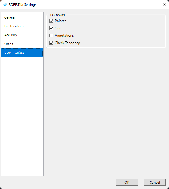
Snaps
You can set the snap direction for the Graphical Station selection tool.
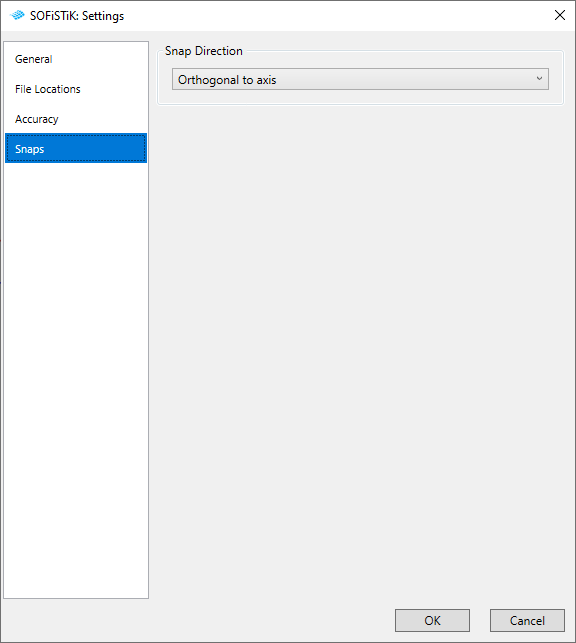
Snap Direction
Orthogonal to Axis - points will be projected orthogonal on the Axis
Projection from Reference - edges, lines will be projected on the axis with the direction of the curves
Curve Intersection - point on the axis is evaluated using the intersection between axis and the curve (from horizontal projection)
Note
Given ‘Absolute’ value is also used as a accuracy control of the imported axis from LandXML file format.