Section Definition In Json Format
Format Description
In this chapter the json format which is used for defining cross sections within the SOFiSTiK Grasshopper Toolkit is described in detail.
Section
Name |
Type |
Structure |
Description |
|---|---|---|---|
Id |
Integer |
Item |
Id of section |
Name |
Text |
Item |
Name of section |
Unit |
Text |
Item |
Unit of section in which 2d distances
are measured. |
MaterialId |
Integer |
Item |
Material number of section. |
Points |
List |
List of section points which make up the geometry of this section |
|
Loops |
List |
List of section loops which define polygonal boundaries of this section |
|
Circles |
List |
List of section circles defining circular boundaries of this section |
|
ThinWalledSegments |
List |
List of thin walled segments defining thin walled section geometry |
|
Variables |
Text / Number |
Map |
Map of variable names and their initial values, this section is depending on |
VariableDescriptions |
Text / Text |
Map |
Optional map of variable names and
a text describing their role inside
the section. |
PointReinforcements |
List |
List of point reinforcements |
|
LineReinforcements |
List |
List of line reinforcements |
|
PerimeterReinforcements |
List |
List of perimeter reinforcements |
Point
Name |
Type |
Structure |
Description |
|---|---|---|---|
Id |
Text |
Item |
Identifier of section point |
Coord |
Text |
List |
List with two elements representing
the Y, Z coordinates of a section point
in two-dimensional space. |
Reference |
Text |
List |
List of reference point ids. |
Type |
Text |
Item |
Type of reference specifying the frame
of reference in which the coordinates
are interpreted. |
R |
Text |
Item |
Optional radius specified as expression
or absolute value, creating a fillet
at this section point. |
F |
Text |
Item |
Equivalent to “R” but instead creating
a chamfer at this section point. |
Loop
Name |
Type |
Structure |
Description |
|---|---|---|---|
Id |
Text |
Item |
Identifier of section loop |
MaterialId |
Text |
Item |
Material number of section loop |
ConstructionStage |
Text |
Item |
Construction stage of section loop |
Points |
List |
List of section points this section loop consists of |
Circle
Name |
Type |
Structure |
Description |
|---|---|---|---|
Id |
Text |
Item |
Identifier of section circle |
MaterialId |
Text |
Item |
Material number of section circle |
ConstructionStage |
Text |
Item |
Construction stage of section circle |
Radius |
Text |
Item |
Radius of circular element as expression or absolute value |
Point |
Item |
Section point where this section circle is located |
ThinWalledSegment
Name |
Type |
Structure |
Description |
|---|---|---|---|
Id |
Text |
Item |
Identifier of thin walled segment |
MaterialId |
Text |
Item |
Material number of segment |
ConstructionStage |
Text |
Item |
Construction stage of segment |
Type |
Text |
Item |
Type of segment. |
Thickness |
Text |
Item |
Thickness of segment as expression or absolute value |
PointStart |
Item |
Section point where the start of this segment is located |
|
PointEnd |
Item |
Section point where the end of this segment is located |
PointReinforcement
Name |
Type |
Structure |
Description |
|---|---|---|---|
Id |
Text |
Item |
Identifier of reinforcement |
Layer |
Text |
Item |
Layer of reinforcement |
MaterialId |
Text |
Item |
Material number of reinforcement |
Diameter |
Text |
Item |
Diameter of reinforcement as expression or absolute value |
TorsionalContribution |
Text |
Item |
Optional torsional contribution. |
Point |
Item |
Section point where this reinforcement is located |
LineReinforcement
Name |
Type |
Structure |
Description |
|---|---|---|---|
Id |
Text |
Item |
Identifier of reinforcement |
Layer |
Text |
Item |
Layer of reinforcement |
MaterialId |
Text |
Item |
Material number of reinforcement |
Diameter |
Text |
Item |
Diameter of reinforcement as expression or absolute value |
TorsionalContribution |
Text |
Item |
Optional torsional contribution. |
Spacing |
Text |
Item |
Minimal distance between each two single reinforcement bars as expression or absolute value |
BarCount |
Text |
Item |
Total amount of single reinforcement bars as expression or absolute value |
BarDistribution |
Text |
Item |
Optional manner in which bars are
distributed along the line. |
PointStart |
Item |
Section point where the start of this line reinforcement is located |
|
PointEnd |
Item |
Section point where the end of this line reinforcement is located |
PerimeterReinforcement
Name |
Type |
Structure |
Description |
|---|---|---|---|
Id |
Text |
Item |
Identifier of reinforcement |
Layer |
Text |
Item |
Layer of reinforcement |
MaterialId |
Text |
Item |
Material number of reinforcement |
Diameter |
Text |
Item |
Diameter of reinforcement as expression or absolute value |
TorsionalContribution |
Text |
Item |
Optional torsional contribution. |
Spacing |
Text |
Item |
Minimal distance between each two single reinforcement bars as expression or absolute value |
BarDistribution |
Text |
Item |
Optional manner in which bars are
distributed along the perimeter. |
Inset |
Text |
Item |
Distance between the section loop and this reinforcement as expression or absolute value |
LoopId |
Text |
Item |
Identifier of section loop where this perimeter reinforcement is located |
Example Sections
Example Solid Section
Here is a small example defining a rectangular section in the json format described above.
{
    "Id": 1,
    "Name": "example-section-solid",
    "Unit": "m",
    "MaterialId": 1,
    "Points":
    [
      { "Id": "ORG",  "Coord": [ 0.0, 0.0 ] },
      { "Id": "TOP",  "Coord": [ 0.0, "-0.5*H" ] },
      { "Id": "BOT",  "Coord": [ 0.0, "+0.5*H" ] }
    ],
    "Loops":
    [
      {
        "Id": "L1",
        "Points":
        [
          { "Id": "P1",  "Coord": [ "+0.50*W", 0.0 ], "Reference": ["TOP"] },
          { "Id": "P2",  "Coord": [ "+0.50*W", 0.0 ], "Reference": ["BOT"], "R": "RO" },
          { "Id": "P3",  "Coord": [ "-0.50*W", 0.0 ], "Reference": ["BOT"], "F": "RO" },
          { "Id": "P4",  "Coord": [ "-0.50*W", 0.0 ], "Reference": ["TOP"] }
        ]
      }
    ],
    "Circles":
    [
      {
        "Id": "C1",
        "Type": "Inner",
        "Point": { "Id": "PC1",  "Coord":  [ 0.0, 0.0 ], "Reference": [ "ORG" ] },
        "Radius": "RI"
      }
    ],
    "Variables": { "W": 4.0,  "H": 3.0, "RI": 0.7, "RO": 0.5, "rfDia": 0.2, "rfSpace": 0.3, "rfInset": 0.5, "rfBDist": 1.0 },
    "VariableDescriptions":
    {
      "W":       "Width:Width of Rectagngle",
      "H":       "Height:Height of Rectagnle",
      "RI":      "RadiusCircle:Radius of inner circular element",
      "RO":      "RadiusCorner:Radius at corner points",
      "rfDia":   "DiameterRf:Diameter of reinforcement",
      "rfSpace": "SpacingRf:Spacing of reinforcement",
      "rfInset": "InsetRf:Inset of reinforcement",
      "rfBDist": "BorderDistRf:Border distance of reinforcement"
    },
    "LineReinforcements":
    [
      {
        "Id": "RF1",
        "Layer": "1",
        "MaterialId": "2",
        "Diameter": "rfDia",
        "BarDistribution": "FULL",
        "Spacing": "rfSpace",
        "PointStart": { "Id": "RFP1", "Coord": [ "rfBDist", "+rfInset" ], "Reference": [ "P2", "P3" ], "Type": "Polar"},
        "PointEnd":   { "Id": "RFP2", "Coord": [ "rfBDist", "-rfInset" ], "Reference": [ "P3", "P2" ], "Type": "Polar"}
      }
    ]
}
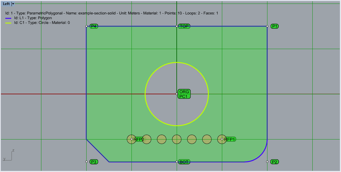
Figure 1. Overview solid section in Rhino
Example Thin Walled Section
And another example defining a thin walled section according predescribed json format.
{
    "Id": 2,
    "Name": "example-section-thinWalled",
    "Unit": "m",
    "MaterialId": 1,
    "ThinWalledSegments":
    [
      {
        "Id": "PTL",
        "Type": "PLAT",
        "PointStart": { "Id": "PTLStart", "Coord": [ 0.0, "+0.5*TH1" ] },
        "PointEnd":   { "Id": "PTLEnd",   "Coord": [ "-0.5*W", "+0.5*TH1" ] },
        "Thickness": "TH1"
      },
      {
        "Id": "PTR",
        "Type": "PLAT",
        "PointStart": { "Id": "PTRStart", "Coord": [ 0.0, "+0.5*TH1" ] },
        "PointEnd":   { "Id": "PTREnd",   "Coord": [ "+0.5*W", "+0.5*TH1" ] },
        "Thickness": "TH1"
      },
      {
        "Id": "PM",
        "Type": "PLAT",
        "PointStart": { "Id": "PMStart", "Coord": [ 0.0, "+TH1" ] },
        "PointEnd":   { "Id": "PMEnd",   "Coord": [ 0.0, "H" ] },
        "Thickness": "TH2"
      },
      {
        "Id": "WM",
        "Type": "WELD",
        "PointStart": { "Id": "WMStart", "Coord": [ 0.0, "+0.5*TH1" ] },
        "PointEnd":   { "Id": "WMEnd",   "Coord": [ 0.0, "+TH1" ] },
        "Thickness": "TH3"
      }
    ],
    "Variables": { "W": 4.0,  "H": 3.0, "TH1": 0.5, "TH2": 0.3, "TH3": 0.1, "rfDia": 0.1, "rfSpace": 0.3, "rfBDist": 0.5 },
    "VariableDescriptions":
    {
      "W":       "Width:Width of section",
      "H":       "Height:Height of section",
      "TH1":     "ThicknessTop:Thickness of top slab",
      "TH2":     "ThicknessMid:Thickness of vertical element",
      "TH3":     "ThicknessWeld:Thickness of weld",
      "rfDia":   "DiameterRf:Diameter of reinforcement",
      "rfSpace": "SpacingRf:Spacing of reinforcement",
      "rfBDist": "BorderDistRf:Border distance of reinforcement"
    },
    "LineReinforcements":
    [
      {
        "Id": "RF1",
        "Layer": "1",
        "MaterialId": "2",
        "Diameter": "rfDia",
        "BarDistribution": "FULL",
        "Spacing": "rfSpace",
        "PointStart": { "Id": "RFP1", "Coord": [ 0.0, "+TH1+rfBDist" ] },
        "PointEnd":   { "Id": "RFP2", "Coord": [ 0.0, "+H-rfBDist" ] }
      }
    ]
}
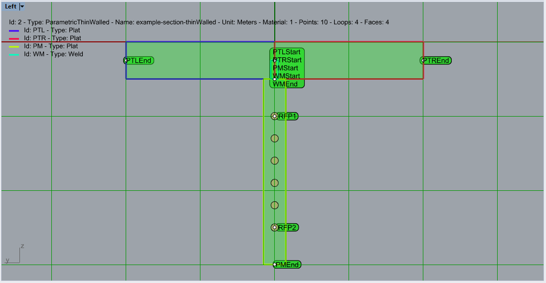
Figure 2. Overview thin walled section in Rhino


