Revit Structure Export to SOFiCAD
The Revit Structure Export program according to SOFiCAD is a product of
SOFiSTiK AG, Bruckmannring 38, D-85764 Oberschleissheim
Tel. 0800 SOFISTIK (0800 - 76347845)Tel. Customer Service 0700-SOFISTIK (0700 - 76347845)Fax Customer Service 089 / 315878-77Customer Services: support@sofistik.de
and is designed as an adaptation of Revit Structure.
Note
If there is no AutoCAD / SOFiCAD installation on the computer, only the “Export only” command is available in the multifunction bar.
Revit export
 Export onlyExport only
Command |
SOF_EXPORT_RVT |
Tooltip |
Exportiert Schalkanten aus Revit. |
The settings are saved as an XML file.
This command exports a drawing data (DWG) and an XML file, starts SOFiCAD and imports the drawings directly into SOFiCAD based on the settings in the XML file.
Revit export only
Export onlyExport onlyCommand |
SOF_EXPORT_RVT |
Tooltip |
Exportiert Schalkanten aus Revit. |
The settings are saved as an XML file.
This command exports a drawing data (DWG) and an XML file.
Note
ATTENTION Only the “Export only” command is available for a SOFiCAD-OEM installation.
Export dialog
The dialog only appears after the call if the active view is a plan view and the Revit Structure project has already been saved. If this is not a plan view or if you have never saved your Revit Structure project, you will receive notification messages.
Description of the dialog box
Save as
In this path you can set the location of the XML and DWG files that are generated by the interface. By default, the program suggests the path in which your Revit Structure project is saved.
mode
Export all (map and viewport)
The XML file and a DWG of each Revit view are generated. The reinforcement plan DWG is created in SOFiCAD and overwritten if necessary!
With the command “Export without calling SOFiCAD”, only the XML file and a DWG of each Revit view are generated.
Only new DWGs of the Revit Plan views are created.
Viewport only (plan remains unchanged)
With the button “Select view window” you can only have certain DWGs of the Revit plan views newly created. In the exported DWG, if it is currently open, the XREFs of the Revit Plan views are reloaded. The change is immediately visible. This mode is recommended if the geometry in the Revit Structure building model has changed and you want to update it in the reinforcement plan DWG. The reinforcement plan DWG itself is still available.
Plan only
Only the reinforcement plan is updated. The DWGs of the Revit Plan views are not newly created. Existing reinforcement in the reinforcement plan is not lost as a result. This mode is recommended if you have changed the arrangement of the Revit plan views and want to update them in your reinforcement plan DWG.
details
AutoCAD drawing template
The set AutoCAD template file (DWT) is used as the basis for generating the reinforcement plan DWG. The XREFs of the Revit plan views are generated based on the standard AutoCAD template file. The drawing units must match the unit of the template file. This setting is important if scenario 1 applies to you.
Layer and properties
If you select “Category properties VONLAYER, overwrites VONELEMENT”, Revit elements with view-specific graphic overrides retain these properties in the CAD application.
If you select “Export all VON-LAYER properties, no overrides”, view-specific graphic overrides in the CAD application are ignored. All exported Revit elements are on the same CAD layer as other elements in the same Revit category. The least layers are created in the DWG file.
If you select “All FROM-LAYER properties, create new layers for overrides”, Revit elements with view-specific graphic overrides are placed on their own CAD layers. This option creates most of the layers in the exported DWG file.
Export rooms and surfaces as a polyline
Revit rooms and surfaces are exported to closed polylines in the CAD DWG
Scaling the line types
If you select “Scaled linetype definitions”, the graphic intentions are retained by exporting the linetypes with scaling according to the view scale.
If “Model area (PSLTSCALE = 0)” is selected, the view scale is set for the LTSCALE parameter and the value 0 for PSLTSCALE.
If “Paper space (PSLTSCALE = 1)” is selected, the value for both parameters, LTSCALE and PSLTSCALE, is set to 1. When scaling Revit linetype definitions, the project units are taken into account, but otherwise they are exported unchanged.
Basis of the coordinate system
If you select “Project internal”, the origin of the export file is set to the internal coordinates of the Revit project.
If you select “Shared”, the origin of the export file is set to the shared position (measurement point) of the Revit project.
An AutoCAD drawing unit is
The setting chosen here affects the creation of the XREF’s (Revit views). The reinforcement plan DWG must also be created with these units.
Note
If you have already exported a Revit plan and would like to repeat this export with other units, please delete the XML file beforehand, which is in the folder in which your already exported reinforcement plan DWG is also located.
Layer settings
Here you select a mapping file that defines which Revit category becomes which layer. The default is a mapping file with the name “Export SOFiCAD_0.txt” adapted to a German SOFiCAD installation. There is another customized mapping file for export to an English SOFiCAD installation.
Or you can select one of the predefined standards from the dropdown box by clicking on the path input:
AIA - American Institues of Architects Standard
ISO 13567 - ISO standard 13567
CP 83 - Singapore Standard 83
BS 1192 - British Standard 1192
Special export settings
In SOFiCAD you can define individual settings for the following elements:
Mapping a Revit dimension type to a SOFiCAD dimension style
Mapping Revit parameters to SOFiCAD attributes
Definition option for the labeling of the viewports on the layout of the reinforcement plan DWG
You make these settings in the file BiMTOOLS_B_USR.ini, which can be found in the user’s AppData directory by default.
Changes are only accepted if the “;” (Semicolon) is removed.
[DIMENSIONSTYLES]
In this section of the INI file, you define which Revit Structure dimension type should be converted to which SOFiCAD dimension style.
Note
If your dimension type in Revit contains a period, a comma or a space, you have to make sure that the export converts these characters into a “_”.
Thus, a dimension type existing in Revit with the name “1.8mm ISOCPEUR” in the INI file must be called “1_8mm_ISOCPEUR”.
In certain situations, which are not described in more detail here, the AutoCAD export creates additional dimension styles. These differ only in the addition of “_1” in the style name. To ensure that the correct SOFiCAD dimensioning styles are used here, you must add this entry to the INI file.
To find out exactly what the AutoCAD style name is called, press the function key “F2” immediately after exporting to SOFiCAD. You will then find a similar section in the text window as shown below.
Dimstyle = 1_8mm_ISOCPEUR
New Dimstyle = SOFI18
Dimstyle = 2_5mm_ISOCPEUR
New Dimstyle = SOFI25
Dimstyle = 1_8mm_ISOCPEUR_1
New Dimstyle = SOFI18
Here you can see that AutoCAD created the style “1_8mm_ISOCPEUR_1” independently. This style would then have to be entered in the INI file as follows:
1_8mm_ISOCPEUR_1 = SOFI18
[TITLEBLOCK]
In this section of the INI file, you link the parameters available in Revit Structure with the attributes of SOFiCAD. This function is specially designed so that title block content from Revit Structure can be transferred directly to SOFiCAD. The settings refer to the standard existing in SOFiCAD. If you deviate from this standard, you have to edit this part of the .ini file.
[VIEWPORTLABELS]
In this section of the INI file, you define the settings on which the Revit viewport label is based in the layout of the exported plan DWG. The position of the label cannot be changed. This is based on the position of the Revit Structure Plan.
You can define the following settings:
PEN4NUMBER - SOFiCAD pin number for the viewport label number
STYLE4NUMBER - Font for the number of the viewport label
PEN4TEXT - Pen number from SOFiCAD for the text of the viewport label
STYLE4TEXT - Font for the text of the viewport label
FORMAT4TEXT - Format the text of the viewport label. The name of the view is saved in the variable “%s” and the scale of the view in the variable “%0.f”. Set your desired formatting using these two parameters.
Scenarios that occur
This section is intended to demonstrate various scenarios that arise in practice and how they work with this function.
Scenario 1:
The reinforcement blanks are exported from Revit Structure from a PC “A” and the reinforcement is created with SOFiCAD.
Note
Revit Structure and SOFiCAD must be installed on PC “A”.
To do this, always use the “SOFiSTiK - SOFiCAD - Export” command. It will automatically through the interface
an XML file that is responsible for the layout and header information
one DWG for each Revit view that exists on the plan to be exported
a reinforcement plan DWG (including the XREF’s of Revit View DWG’s)
generated. You can immediately start creating the reinforcement in the DWG reinforcement plan, since SOFiCAD is automatically called up with the created reinforcement plan DWG.
Scenario 2:
The reinforcement blanks are exported from Revit Structure from a PC “A” and the reinforcement from SOFiCAD is created from a PC “B”, but both PCs are in the same network.
For this, the PC “A” in Revit Structure uses the command “SOFiSTiK - SOFiCAD - commands - export without calling SOFiCAD”. A drive path to which PC “A” and PC “B” have access is set via the export dialog. It will automatically enter this directory through the interface
an XML file that is responsible for the layout and header information
one DWG for each Revit view that exists on the plan to be exported
generated.
On PC “B” you start SOFiCAD with a corresponding template file and call the command there
SOF_IMPORT_RVT or via the ribbon “Construction II”
on. One selects the XML file from the folder in the PC “A” which has stored the files described above. With the help of the XML file, this function now creates the reinforcement plan DWG (including the XREFs of the Revit view DWGs) and saves them in the same directory.
Scenario 3:
The reinforcement blanks are exported from Revit Structure from a PC “A” and the reinforcement is generated from SOPCCAD from a PC “B”, both PCs are not in the same network.
For this, the PC “A” in Revit Structure uses the command “SOFiSTiK - SOFiCAD - commands - export without calling SOFiCAD”. Any drive path is set via the export dialog. It will automatically enter this directory through the interface
an XML file that is responsible for the layout and header information
one DWG for each Revit view that exists on the plan to be exported
generated.
Now PC “A” sends this generated data to PC “B”.
On PC “B” you start SOFiCAD with a corresponding template file and call the command there
SOF_IMPORT_RVT or via the ribbon “Construction II”
on. You select the XML file from the folder in which you have stored the data from PC “A”. With the help of the XML file, this function then creates the reinforcement plan DWG (including the XREFs of the Revit view DWGs) and saves them in the same directory.
Note
In order for PC “A” to use the functions “Export everything, only viewport, only plan” described under S. PC “A” needs the reinforcement plan DWG generated by PC “B”. This must also be replaced and stored under PC “A” in the same directory as the XML file described above. The name of the XML file and the name of the DWG reinforcement plan must also be identical!
..todo:: Doku oberhalb und unterhalb zusammenführen!
RS Importiert aus PDF Doku
Icon |
Multifunktionsleiste |
Brief description |
|---|---|---|
SOFiSTiK -> SOFiCAD |
||
Export |
Der Exportdialog (s. S. 6) erzeugt eine .xml-Datei mit wichtigen Informationen für SOFiCAD und jeweils einer DWG pro exportierter Revit Ansicht. In SOFiCAD muss der Befehl „Konstruktion II – Revit – Revit import“ verwendet werden und die exportierte *.xmlDatei ausgewählt werden. Die einzelnen exportierten Revit Ansichten (DWG’s) werden automatisch als XREF in der Bewehrungs-DWG angelegt. |
|
Befehle Hilfe anzeigen (Deutsch) Log-Dateien anzeigen |
Hierunter befinden sich Hilfe-Dateien und LogFiles. Öffnet dieses Hilfedokument in Deutsch Öffnet eine Log-Datei in der die aktuellsten Neuerungen der Software nachzulesen sind. Diese sind ggf. in diesem Handbuch nicht dokumentiert! |
Export dialog
Über diesen Dialog werden wesentliche Dinge des Exports eingestellt. Im Folgenden werden diese Einstellmöglichkeiten detailliert beschrieben.
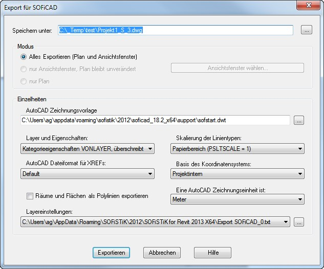
Bild 2: Dialog: Export für SOFiCAD
Der Dialog erscheint nach dem Aufruf nur, wenn die aktive Ansicht eine Planansicht ist und das
Revit Structure Projekt bereits gespeichert wurde. Sollte dies keine Planansicht sein, oder haben
Sie Ihr Revit Structure Projekt noch nie gespeichert, erhalten Sie jeweils Hinweismeldungen.
Beschreibung des Exportdialogs
Dialogabschnitt |
Description |
|---|---|
Exportdialog (Aufruf mit SOFiSTiK -> SOFiCAD -> Export) |
|
Speichern unter |
Unter diesem Pfad stellen Sie den Speicherort der Dateien (.xml, .dwg) ein, welche durch die Schnittstelle erzeugt werden. Standardmäßig schlägt Ihnen das Programm den Pfad vor, indem Ihr Revit-Structure Projekt gespeichert ist. |
Modus: |
|
Export all (map and viewport) Viewport only (plan remains unchanged) Plan only |
Es wird die .xml-Datei und jeweils eine DWG jeder Revit Ansicht erzeugt. Es werden nur neue DWG’s der Revit Plan Ansichten erzeugt. Über den Schalter “Ansichtsfenster wählen” können Sie nur bestimmte DWG’s der Revit Plan Ansichten neu erzeugen lassen. In der exportierten DWG werden, falls diese gerade geöffnet ist, die XREF’s der Revit Plan Ansichten neugeladen. Somit werden die Änderung sofort sichtbar. Dieser Modus ist zu empfehlen wenn sich die Geometrie im Revit Structure Gebäudemodell geändert hat und man diese in der Bewehrungsplan DWG aktualisieren möchte. Die Bewehrungsplan DWG selbst steht unverändert zur Verfügung. Only the reinforcement plan is updated. The DWGs of the Revit Plan views are not newly created. Existing reinforcement in the reinforcement plan is not lost as a result. This mode is recommended if you have changed the arrangement of the Revit plan views and want to update them in your reinforcement plan DWG. |
Einzelheiten: |
|
AutoCAD drawing template |
Die eingestellte AutoCAD Vorlagendatei (.dwt) wird als Grundlage für die Erzeugung der Bewehrungsplan DWG verwendet. Die XREF’s der Revit Plan Ansichten werden auf Basis der Standard AutoCAD Vorlagendatei erzeugt. Die Zeichnungseinheiten müssen der Einheit der Vorlagendatei übereinstimmen. Diese Einstellung ist von Bedeutung falls Szenario 1 (s. S 11) bei Ihnen zutrifft. |
Layer und Eigenschaften: Kategorieeigenschaften VONLAYER, überschreibt VONELEMENT Alle Eigenschaften VONLAYER exportieren, keine Überschreibungen |
Revit-Elemente mit ansichtsspezifischen grafischen Überschreibungen behalten diese Eigenschaften in der CAD-Anwendung bei. Ansichtsspezifische grafische Überschreibungen werden in der CAD-Anwendung ignoriert. Alle exportierten Revit-Elemente befinden sich auf demselben CAD-Layer wie andere Elemente derselben Revit-Kategorie. Es entstehen somit am wenigsten Layer in der DWG-Datei. |
Alle Eigenschaften VONLAYER, neue Layer für Überschreibungen erstellen |
Revit-Elemente mit ansichtsspezifischen grafischen Überschreibungen werden auf jeweils eigene CAD-Layer platziert. Diese Option erzeugt die meisten Layer in der exportierten DWG-Datei. |
|---|---|
AutoCAD Dateiformat: R2013 R2010 R2007 R2004 R2000 |
Die XREF’s (Revit-Ansichten) werden im DWG-Dateiformat 2010 erzeugt Die XREF’s (Revit-Ansichten) werden im DWG-Dateiformat 2010 erzeugt Die XREF’s (Revit-Ansichten) werden im DWG-Dateiformat 2007 erzeugt Die XREF’s (Revit-Ansichten) werden im DWG-Dateiformat 2004 erzeugt Die XREF’s (Revit-Ansichten) werden im DWG-Dateiformat 2000 erzeugt. Hierbei werden die Layer-Namen auf 32 Zeichen begrenzt. Revit schneidet längere Namen automatisch ab, wobei die ersten 15 Zeichen und die letzten 15 Zeichen getrennt durch Unterstriche (_) beibehalten werden und ein eindeutiges numerisches Zeichen angehängt wird. |
Räume und Flächen als Polylinie exportieren |
Revit rooms and surfaces are exported to closed polylines in the CAD DWG |
Skalierung der Linientypen: Skalierte Linientypdefinitionen Modellbereich (PSLTSCALE = 0) Papierbereich (PSLTSCALE = 1) |
Bei dieser Option bleiben die grafischen Absichten erhalten, indem die Linientypen mit der Skalierung nach Ansichtsmaßstab exportiert werden. Bei dieser Option wird für den Parameter LTSCALE der Ansichtsmaßstab und für PSLTSCALE der Wert 0 festgelegt Mit dieser Option wird der Wert für beide Parameter, LTSCALE und PSLTSCALE, der Wert 1 festgelegt. Bei der Skalierung von Revit-Linientypdefinitionen werden die Projekteinheiten berücksichtigt, ansonsten werden sie jedoch unverändert exportiert |
Basis der Koordinatensystems: Projektintern Gemeinsam |
Bei dieser Option wird der Ursprung der Exportdatei auf die internen Koordinaten des Revit-Projekts gesetzt. Bei dieser Option wird der Ursprung der Exportdatei auf die gemeinsam genutzte Position (Vermessungspunkt) des Revit- Projekts gesetzt. |
Eine AutoCAD Zeichnungseinheit ist: Meter Centimeter Millimeter |
Die XREF’s (Revit-Ansichten) werden in Meter erzeugt. Die Bewehrungsplan DWG muss ebenfalls in Metern erzeugt werden. Die XREF’s (Revit-Ansichten) werden in Zentimeter erzeugt. Die Bewehrungsplan DWG muss ebenfalls in Zentimeter erzeugt werden. Die XREF’s (Revit-Ansichten) werden in Millimeter erzeugt. Die |
Bewehrungsplan DWG muss ebenfalls in Millimeter erzeugt werden. Wichtig: Sofern Sie bereits einmal einen Export eines Revit Plan gemacht haben und Sie möchten nun diesen Export entweder in Millimeter oder Zentimeter machen, löschen Sie bitte vorher die .xml-Datei, welche in dem Ordner liegt indem auch Ihre bereits exportierte Bewehrungsplan DWG liegt. |
|
Layereinstellungen: Pfad zu einer Layer-MappingDatei |
Mit dieser Option wählen Sie eine Mapping-Datei die definiert, welche Revit Kategorie zu welchem Layer wird. Voreingestellt ist hier eine auf eine deutsche SOFiCAD Installation angepasste Mapping-Datei mit dem Namen “Export SOFiCAD_0.txt. Es existiert eine weitere angepasste Mapping-Datei für einen Export in eine englische SOFiCAD Installation. Or you can select one of the predefined standards from the dropdown box by clicking on the path input: AIA - American Institues of Architects Standard ISO 13567 - ISO standard 13567 CP 83 - Singapore Standard 83 BS 1192 - British Standard 1192 |
Special export settings
In SOFiCAD you can define individual settings for the following elements:
Mapping a Revit dimension type to a SOFiCAD dimension style
Mapping Revit parameters to SOFiCAD attributes
Definitionsmöglichkeit für die Beschriftung der Ansichtsfenster auf dem Layout der Bewehrungsplan
DWG
Diese Einstellungen treffen Sie in der Datei BiMTOOLS_B_USR.ini, die standardmäßig unter dem folgenden Verzeichnis zu finden ist:
%USERPROFILE%AppDataRoamingSOFiSTiK2018SOFiCAD_50_x64support
Changes are only accepted if the “;” (Semicolon) is removed.
Einstellung |
Möglichkeiten |
|---|---|
[DIMENSIONSTYLES] |
In diesem Abschnitt der .ini-Datei definieren Sie welcher Bemaßungstyp von Revit Structure in welchen SOFiCAD Bemaßungsstil konvertiert werden soll. Wichtig: Sollte Ihr Bemaßungstyp in Revit ein Punkt, ein Komma oder eine Leerstelle beinhalten, so müssen Sie darauf achten, dass der Export diese Zeichen in einen “_” wandelt. Somit muss ein in Revit existierender Bemaßungstyp mit dem Namen “1,8mm ISOCPEUR” in der .ini-Datei “1_8mm_ISOCPEUR” heißen. In bestimmten Situationen, die hier nicht näher beschrieben werden, erzeugt der AutoCAD Export zusätzliche Bemaßungsstile. Diese unterscheiden sich dann nur durch den Zusatz “_1” im Stilnamen. Damit hier ebenfalls die richtigen SOFiCAD Bemaßungsstile verwendet werden müssen Sie die .ini-Datei um diesen Eintrag erweitern. To find out exactly what the AutoCAD style name is called, press the function key “F2” immediately after exporting to SOFiCAD. You will then find a similar section in the text window as shown below. Dimstyle = 1_8mm_ISOCPEUR New Dimstyle = SOFI18 Dimstyle = 2_5mm_ISOCPEUR New Dimstyle = SOFI25 Dimstyle = 1_8mm_ISOCPEUR_1 New Dimstyle = SOFI18 Hier sieht man das AutoCAD den Stil “1_8mm_ISOCPEUR_1” selbstständig angelegt hat. Dieser Stil wäre dann in der .ini-Datei folgendermaßen nachzutragen: 1_8mm_ISOCPEUR_1=SOFI18 |
[TITLEBLOCK] |
In diesem Abschnitt der .ini-Datei verknüpfen Sie die in Revit Structure verfügbaren Parameter mit den Attributen von SOFiCAD. Diese Funktion ist speziell dafür vorgesehen, dass Plankopfinhalte aus Revit Structure direkt in SOFiCAD übergeben werden können. Die Einstellungen beziehen sich auf den in SOFiCAD existierenden Standard. Wenn Sie von diesem Standard abweichen, so müssen Sie diesen Teil der .ini-Datei bearbeiten. |
|---|---|
[VIEWPORTLABELS] PEN4NUMBER STYLE4NUMBER PEN4TEXT STYLE4TEXT FORMAT4TEXT |
In diesem Abschnitt der .ini-Datei definieren Sie auf welchen Einstellungen die Ansichtsfensterbeschriftung von Revit im Layout der exportierten Plan-DWG beruht. Dabei kann die Position der Beschriftung nicht geändert werden. Diese beruht auf der Position des Revit Structure Plans. Folgende Einstellungen können Sie definieren: Stift Nummer von SOFiCAD für die Nummer der Ansichtsfensterbeschriftung Schriftart für die Nummer der Ansichtsfensterbeschriftung Stift Nummer von SOFiCAD für den Text der Ansichtsfensterbeschriftung Schriftart für den Text der Ansichtsfensterbeschriftung Formatierung des Textes der Ansichtsfensterbeschriftung. Hierbei wird der Name der Ansicht in der Variable “%s” und der Maßstab der Ansicht in der Variable “%0.f” gespeichert. Stellen Sie Ihre gewünschte Formatierung unter Verwendung dieser beider Parameter ein. |


