Aligned/Polar References
 Aligned/Polar References
Command |
SOF_CM_PUNKTAUFLINIE |
Tooltip |
This can be used to determine a distance to perpendicular and offset distance relative to another cross section point. |
Sidebar |
Cross Section Editor |
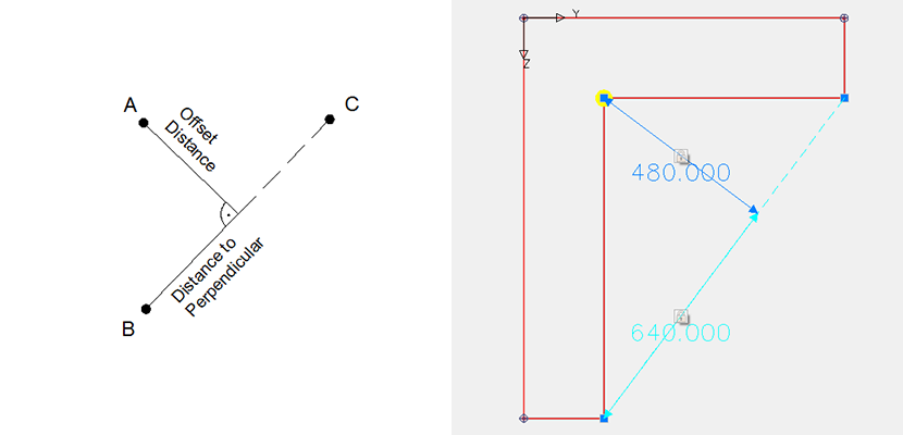
Determines the coordinates of a dependent point A with a straight line between two reference points B and C and with the input of the distance to perpendicular and the offset distance relative to point B.
The distance to perpendicular and the offset distance can be defined parametrically when using a variable or formula. The parametric input can be assigned only when editing the input of the points.
The points B and C can be also dependent points.
If the coordinates of the points B and C (e.g. because they are dependent points) change, then there are two options for the behaviour of the distance to perpendicular and the offset distance:
Absolute definition: The length of the distance to perpendicular or the offset distance does not dependent on change in length of the line BC.
Relative definition: The length of the distance to perpendicular and the offset distance is modified with the factor of the change in length in line BC.
Example:
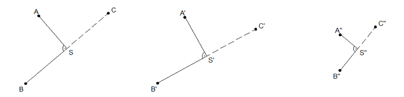
The positions of points B and C have been modified along a geometric axis to B’ and C’, or to B’’ and C’’ (because points B and C have been defined as dependent points). Accordingly, the length of line B’C’ or B’’C’’ has changed from the original length of line BC. (It is assumed that the parameters for the distance to perpendicular and the offset distance are constant.)
In absolute mode, the lengths remain the same, i.e. AS=A’S’ and BS=B’S’.
In relative mode the length AS is multiplied by a ratio of B’’C’’/BS so that the result is AS * B’’C’’/BS = A’’S’’ and similarly BS * B’’C’’/BS =B’’S’’.
Note
Absolute and relative modes can be switched separately for the distance to perpendicular and the offset distance. For the offset distance, the relative mode is available only when the distance to perpendicular operates in relative mode.
Input
At first a point has to be defined whose coordinates are to be used initially as a reference point (point A in the diagram). This point may remain in a fixed/explicitly specified location or can be modified subsequently so that its location is dependent on the parametric input relative to the line BC and the values define the horizontal and vertical distances.
Then a second cross section point (point B in the diagram) can be input. This point is used to measure the distance to the intersection with the perpendicular.
Finally, a third point (point C in the diagram) has to be defined for the second reference point of the straight line BC. The perpendicular distance between point A and the straight line BC is measured and displayed.
If a point which was not yet created as a “cross section point” is to be used for a reference point, then a geometry point can be generated at this position.
Symbolism
The defined references are displayed now symbolically. The double arrows symbolise the defined horizontal distances or the vertical distances. The labelling of the arrows displays either a numerical value (fixed distance; numerical value is the distance currently shown in the cross section), or a variable name or formula (variable distance).
Reference points are represented by a blue triangle and dependent points by a yellow circle.
Editing
Dependent points are marked by a circle with a diagonal cross within. By left clicking on this symbol, the entire reference object is shown. Then it can be edited according to the following procedure:
The reference points and the dependent point can be moved by left-clicking on the object and by pulling of the point to another (permissible) cross section point position.
Beside the double arrows there is a lock symbol. Due to left-clicking on the lock symbol in this display the field is unlocked for editing. It is possible to switch to the variable reference point mode.
Left-clicking on the lock symbol in this display unlocks the field for editing and switches into the mode for a variable reference point mode.
A further left-click on the lock symbol closes the lock and switches back to the fixed input mode, i.e. the distance is fixed and corresponds again to the actual distance in the master cross section, and the parametric input for the distance is quasi-deactivated.
The switch for changing between absolute and relative references appears only for the distance of perpendicular. If it is set here as ‘rel’ (relative input), it can be also switched consequently between absolute and relative operation for the offset distance.
The green tick confirms the input.
The red cross cancels the dialog.
Note
If only the horizontal or the vertical value should be variable, only the corresponding reference should get a variable or formula.
Deleting
A reference can be selected by left-clicking on the reference symbol and then it can be deleted by using the delete key or with the AutoCAD delete command.


