Balanced Cantilever Bridge
Introduction
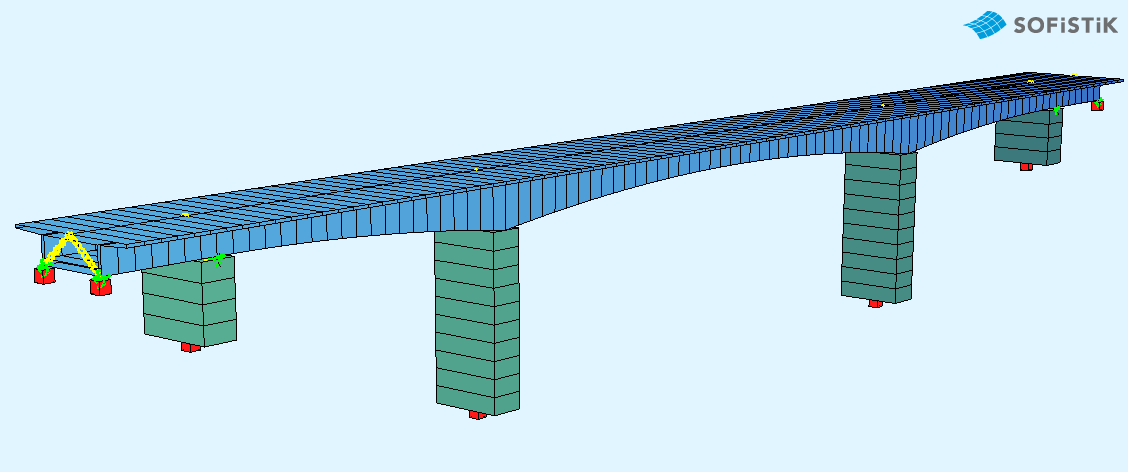
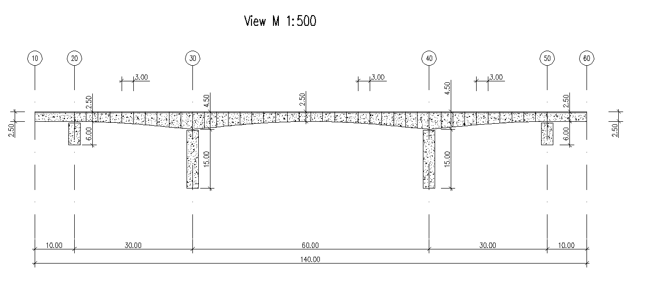
This tutorial deals with a simple 5-span balanced cantilever bridge. The analytical model of the bridge consists of beam elements.
Note
A basic SOFiSTiK knowledge is required for this tutorial. The standard workflow is explained inside the General Workflow description. Inside this tutorial we show only the project specific workflows, which are different from the basic workflow.
Objectives:
Starting a new project
Define Materials
Define Cross Sections
Generate System and Loads inside SOFiPLUS
Linear analysis
Live load analysis
Construction Stages
Design
Project Description
The idea of this tutorial is to guide you through a balanced cantilever bridge project and introduce the general work-flow showing the necessary program tools and functions. All steps like modeling, loading, traffic loads, combinations etc. are simplified.
Note
If there are any hints of new tasks that have to be modified manually (new tasks named “Text Editor (Teddy)”) you find further information’s directly in those tasks. Please open data files related to the chapter.
Bridge Materials:
Number |
Title |
Strength |
|---|---|---|
1 |
Concrete bridge deck |
C 40/50 |
11 |
Concrete piers |
C 40/50 |
2 |
Reinforcement steel |
B 500 B |
3 |
Prestressing steel |
Y 1770 |
4 |
Reinforcement steel stirrups |
B 500 B |
Cross sections
Number |
Title |
Dimensions |
|---|---|---|
1 |
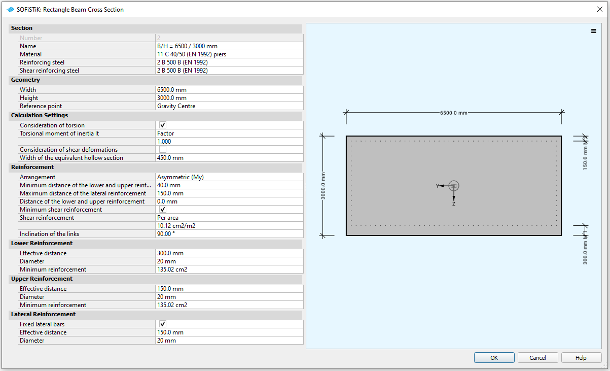
Column [mm] |
b/h=6500/3000 |
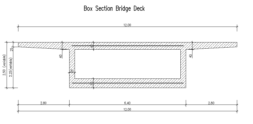
The bridge cross-section at station (10 m):
Construction stages
Stage Number |
Title |
|---|---|
10 |
Activating group 40, 50 and group 1 |
11 |
Prestressing in the Stage |
15 |
Creep in construction |
20 |
Activating group 2 |
21 |
Prestressing in the Stage |
25 |
Creep in construction |
30 |
Activating group 3 |
31 |
Prestressing in the Stage |
35 |
Creep in construction |
40 |
Activating group 4 |
41 |
Prestressing in the Stage |
45 |
Creep in construction |
50 |
Activating group 5 |
51 |
Prestressing in the Stage |
55 |
Creep in construction |
60 |
Activating group 6 |
61 |
Prestressing in the Stage |
65 |
Creep in construction |
70 |
Activating group 7 |
71 |
Prestressing in the Stage |
75 |
Creep in construction |
80 |
Activating group 8 |
81 |
Prestressing in the Stage |
85 |
Creep in construction |
90 |
Activating group 9 |
95 |
Creep in construction |
100 |
Activating group 10 |
105 |
Creep in construction |
110 |
Activating group 11, 20, 30 |
115 |
Creep in construction |
120 |
Activating group 12, 60, 70 |
121 |
Prestressing |
125 |
Creep in construction |
130 |
Activating additional load |
135 |
Creep until t-infinite |
Design code
This tutorial is based on Eurocode EN 1992.
Starting a new project
First we create a new SSD project and save it inside a project directory on your local computer. For further information see chapter Start New SSD Project in the General Workflow description.
Defining materials
Generate all necessary materials listed above. Follow the procedures explained in chapter Material Definition in the General Workflow description.
Defining Cross Sections
In this project we do have only one standard cross section for the pier. Please generate a new rectangular cross section with the dimensions and material properties listed above. Follow the procedures explained in Cross Section Definition in General Workflow description.
The main bridge section will be defined graphically inside SOFiPLUS with the cross section editor.
Note
The deck cross section is varying in height along the length of the bridge. Instead of having to create many cross sections with different heights, a variable is assigned to the height which is varied along the length of the bridge. This variable will be defined within the bridge axis definition in SOFiPLUS. Therefore we recommend to create the bridge axis with all settings first.
Prestressing systems
Please generate a new prestressing system number 1, with a VSL 6-7 multistrand system, see picture below.
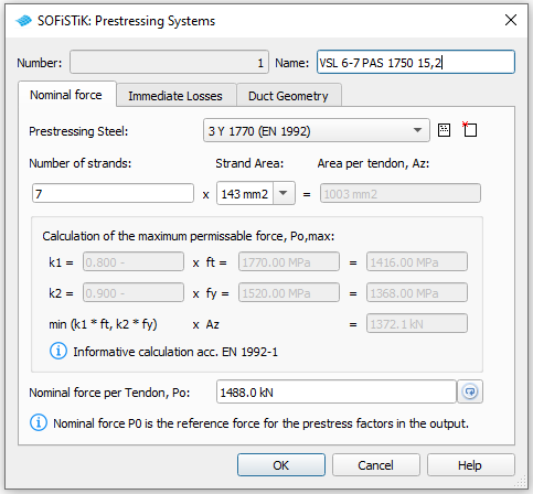
Follow the procedure explained in chapter Prestressing System in the General Workflow description.
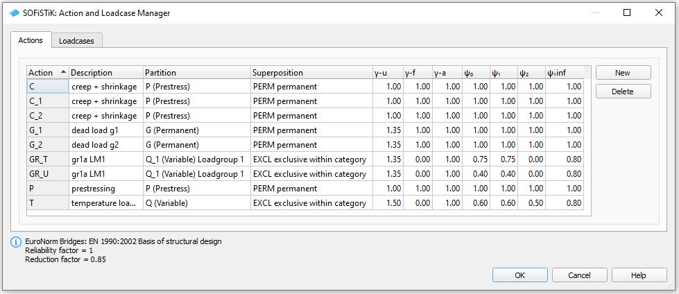
Actions
Before we define any load, we must define all necessary actions within the SSD ” Action Manager”. In our bridge example we need the following actions.
System Generation in SOFiPLUS
The bridge geometry will be defined using the CABD concept inside SOFiPLUS. For that we will work through the following steps:
Define main bridge axis
Define placements along the bridge axis for supports and between all bridge segments
Define variables (will be used for the main cross section)
Generate master cross section within Cross Section Editor
Generate structure lines representing the main bridge construction
Use the Cross Members Editor to generate the support construction containing springs and couplings
Make a final check of the system and align elements if necessary
The following videos will show the main steps to generate the system.
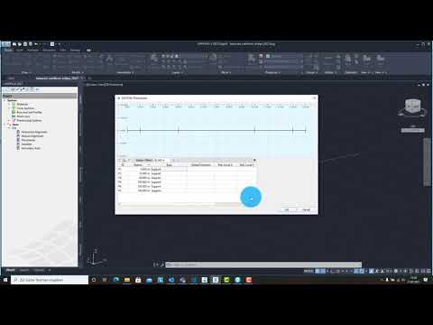
Generate Bridge Axis
The following video will show the axis generation workflow.
Generate Master Cross Section
The following video will show cross section generation workflow within the cross section editor.
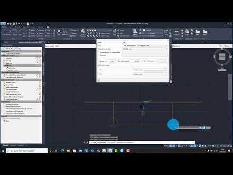
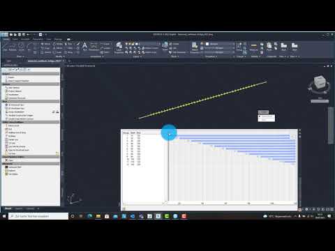
System Generation
The following video will show the system generation workflow.
Tendon Generation
In this tutorial we show the possibility to define tendons via CADINP with the module TENDON.
Hint
For information about graphical tendon generation with SOFiPLUS take a look at the corresponding chapter in our tutorial Post Tensioned Concrete Beam Bridge
The definition comprises the following parts resp. code blocks (see manual of module TENDON for further explanation of commands)
First we define the reference axis.
AXES NOH 1 TYPE REFX SYS KIND -
Then we define the top positions of the geometry
TOPP SP         S  NOH=1 KIND=REFX $ with S = station on axis in m
      0         0   $ excess
      1         0   $ bearing line
      2        10   $ bearing line
      3        40   $ bearing line
      4       100   $ bearing line
      5       140   $ bearing line
      6       140   $ excess
3) Next we define the individual tendons. For a more compact input we use the #define command. This enables us to define a code block that can be repeated with #include. Inside the #define block we use several variables, which we change each time we repeat the code block. In this way we simplify the input and keep the overview of the relevant properties of each tendon.
#define tendon
 TGEO NOG #tendon_NOG NOH 1 NOPS 1 TITL 'Tendon #tendon_NOG'

PTUV TYPE     S                  U     V
     REFX     #xm-#stage_length  #u    #v
     REFX     #xm                #u    #v
     REFX     #xm+#stage_length  #u    #v

CS ICS1 #ncs ICS2 #ncs+1 0
PSIG KIND le ANWS 'TS' KAPA 1.5
TEND NOT #tendon_NOG NOG #tendon_NOG NTEN #nten LC #lc_tendon TYPE REFX  TITL 'Tendon #tendon_NOG'
#enddef
The definition of the variables and the tendon then looks like this:
$ Construction stage 11
let#nten 3          $ number of tendons (for eacg cross-section half)
let#stage_length 6  $ [m] length of the current stage in both directions
let#ncs 11          $ construction stage number. Note: step 2, see ICS1,2
let#lc_tendon 11    $ storagenumber of prestressing forces, no "real" loadcase

let#tendon_NOG 1    $ number of tendon geometry
let#u 3.0           $ horizontal distance from reference axis, visibilty reason
#include tendon

let#tendon_NOG 21   $ number of tendon geometry
let#u -3.0          $ horizontal distance from reference axis, visibilty reason
#include tendon
In this way we define the tendons that run in the top slab of our cross-section and are activated in the construction stages (take a look at the task “Tendon - Top” in the example file).
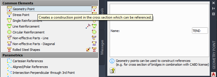
We also want to define tendons in the bottom slab of the cross-section. The position of the bottom slab changes due to the variable cross-section height. Therefore we want to make these tendons follow the change in cross-section geometry. For this purpose we go to SOFiPLUS and define a geometry point in the middle of the bottom slab and give it the name TEND:
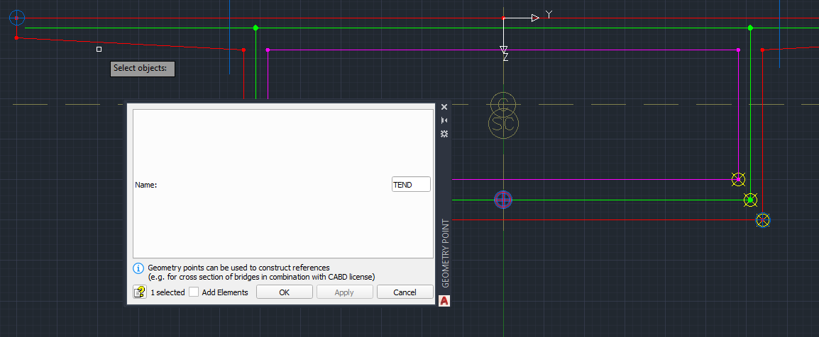
We have to create a cartesian reference to the bottom corner of the cross-section to make the point follow the variable cross-section height.
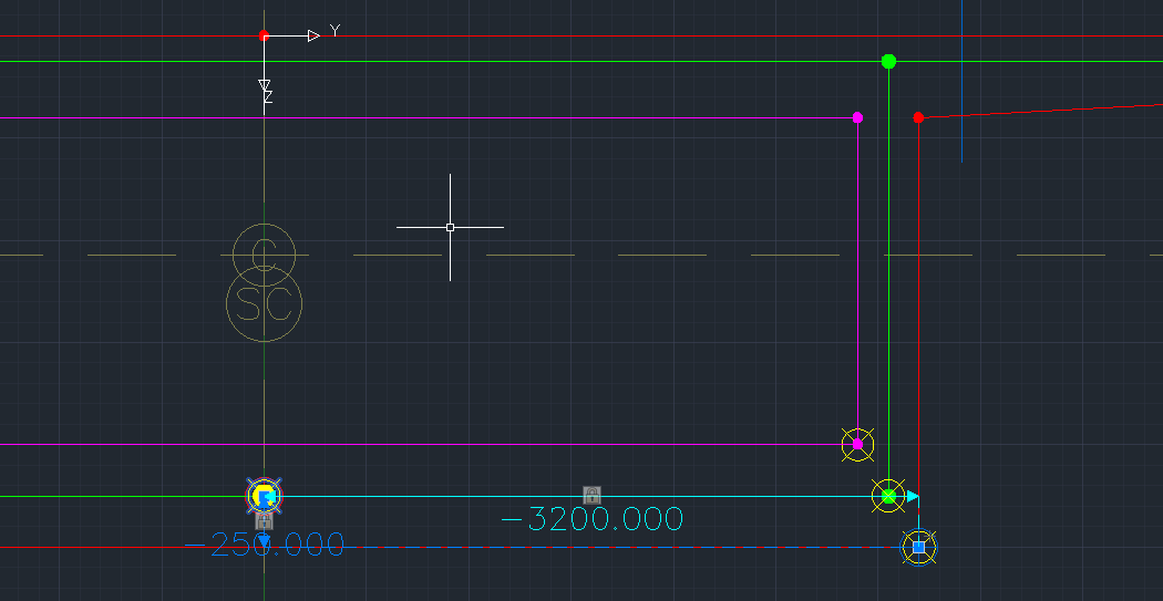
We can then reference this point in our tendon definition with PTUV … CSP (take a look at the task “Tendon - Bottom” in the example file):
PTUV TYPE REFX S 0 V 0 CSP 'TEND'
Note
If we define the tendons in this way wtih CADINP, we do not need to define loadcases to store the curvature loadings before the tendon definition. This loadcases will be created with the numbers specified with TEND … LC.
Loads
In our bridge example we need the following load cases:
After defining the load cases we generate the loads in SOFiPLUS. First we select an element related line load. Defining the load we select the structural lines and define a line load of 10 kN/m for the additional dead weight (loadcase 2).
Warning
Load cases which will be used later on inside the CSM should be saved within the action container NONE. With this concept the load cases will not be used twice in case the user defines his own combination rules using actions only!
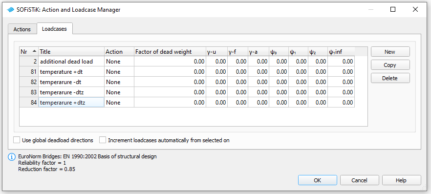
In this example we also generate 4 loadcases (81 to 84) containing the basic temperature loads
LC |
Action |
Designation |
|---|---|---|
81 |
NONE |
constant temperature DT = + 20°C |
82 |
NONE |
constant temperature DT = - 20°C |
83 |
NONE |
temperature difference DTZ = -12.3°C |
84 |
NONE |
temperature difference DTZ = +8.0°C |
For further information about the definition of loads (temperature, settlements, etc.) please see the chapter Define Actions and Loads in the General Workflow description.
Linear Analysis
The linear analysis will be processed automatically for all defined loads. Therefore the selection must be done manually. Please see the chapter Linear Analysis in the General Workflow description.
Generate Envelope from Traffic Loads
As already explained in the general workflow it is necessary to run at least one linear load case before evaluating the traffic loads with the influence line method. We recommend to do this analysis before the construction stage analysis to use the full developped stiffnes matrix from the complete bridge.
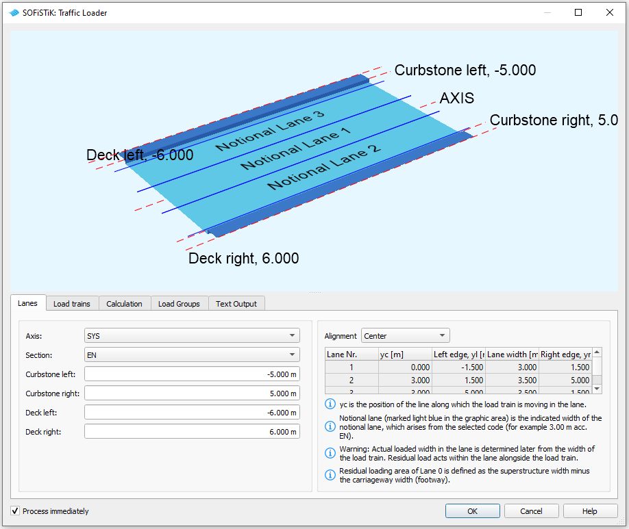
For a general description of the input workflow please see also the chapter Traffic Loads in the General Workflow description. First you select an existing bridge axis and define the width of the traffic lane and bridge. The program will automatically generate all possible lanes.
Next you define the load trains and the desired results. In our case we are interested only in the beam results for further design of the cross sections.
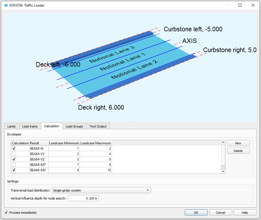
For the results it is necessary to define different load groups and evaluation cases. Usually it is convenient to separate the results for tandem axes and udl loads. The evaluation results will be saved again in predefined action container.
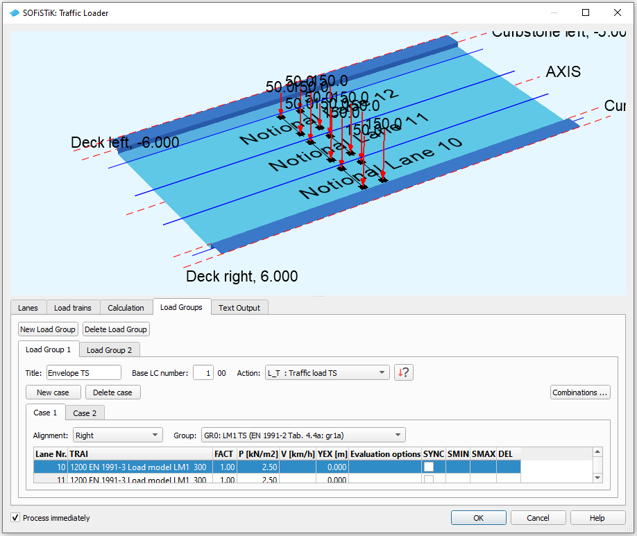
The loads on the footway will be defined as an extra evaluation case inside the UDL load group. In that case we need special combinations from UDL and Footway loads. Simply use the combination button inside the dialogue and generate the combinations. After the input is correct and finished you may close the dialogue and process immediately the analysis. Again we recommend to add a task “Interactive Graphic” to display the important results.
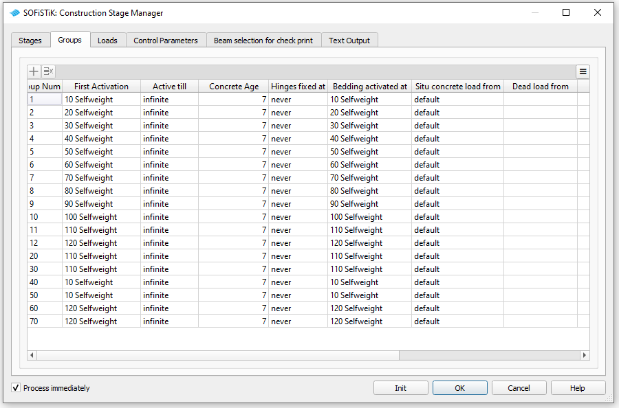
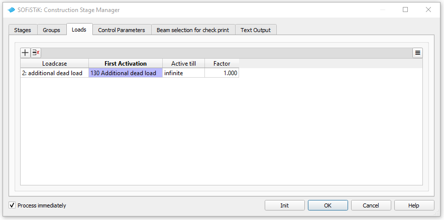
Define Construction Stages
For the computation of the construction stages, the effects of prestress and creep and shrinkage we will use the the “Construction Stage Manager”. Insert the SSD task “Construction Stages”. If you have already assigned construction stages to groups in the system definition in SOFiPlUS (as shown in the corresponding video in this tutorial), you will notice that these settings are taken over by the “Construction Stage Manager”. Construction stages related to prestressing are also taken over if you have already defined your tendons (see above). Constrcution stages for the computation of creep and shrinkage are also added (with our recommended numbering). Now you just have to check your assigments, adjust the settings for creep and shrinkage stages and the group settings. You also have to add construction stages that are not related to groups (as for example in our case construction stage 130 where the additional dead load is activated) and assign the corresponding loads.
The final settings will for our example look like this:
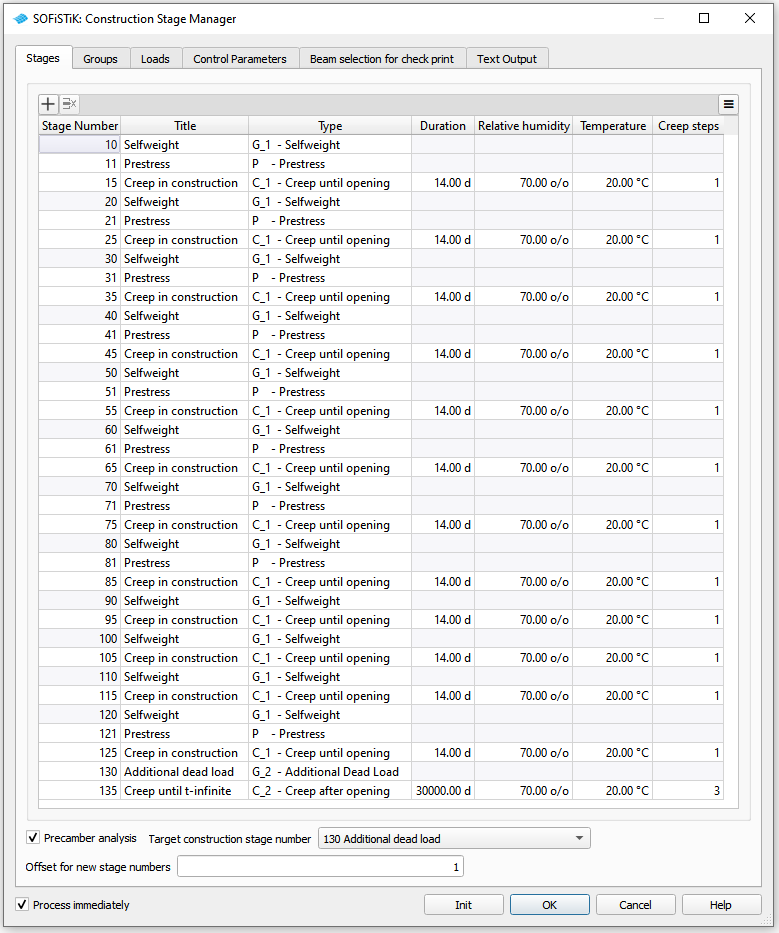
For further explanations please see also the chapter Construction Stages in the General Workflow description and the manual of module CSM.
Combinations
Please follow the explanations of chapter Combinations and Superpositioning from the General Workflow description.
Design
Please follow the explanations of chapter Design Checks from the General Workflow description.
Documentation
For the final documentation, you can collect all single reports and generate a complete document. Please follow the explanations of chapter Generate Report from the General Workflow description.


