Portal frame
Introduction
This tutorial deals with a simple single-span portal frame design according to EN 1993-1-1. The main object of this tutorials is to present the workflow for SOFiSTiK 2022.
This project is fully done using Graphical User Interface (GUI). However it could be completely reproduced via text input - CADINP language.
Hint
This tutorial is based on EN 1993-1-1 and EN 1993-1-5.
Tip
If you click on the figure it will show up in original size.
Tip
The YouTube tutorial videos are recorded with resolution 1920x1080 (1080p Full HD), therefore it is recommended to set the YouTube Quality to 1080p when watching the videos.
Project description
Geometry
The proposed frame is defined as shown below. The haunch length is assumed to be 10% of the span. The portal frames are spaced at 8 m. The cladding of the roof and walls is supported by purlins and side rails. The spacing of the girts and purlins, and the location of restraints to the inside flanges, will be defined at the design stage.
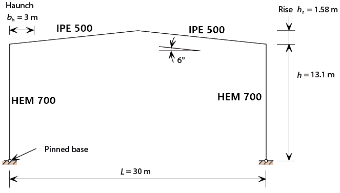
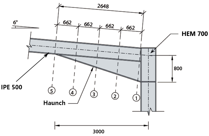
Haunches:
Materials
Number |
Grade |
Notes |
|---|---|---|
1 |
S 355 (EN 1993) |
tf > 16 mm, thus fy = 345 MPa |
Cross-sections
Number |
Title |
Notes |
|---|---|---|
1 |
HEM 700 |
Column |
2 |
IPE 500 |
Rafter |
3 |
Haunch - 463 mm |
IPE 500 + cutting of IPE 500 (average cutting depth 463 mm) |
4 |
Haunch - 340 mm |
IPE 500 + cutting of IPE 500 (average cutting depth 340 mm) |
5 |
Haunch - 204 mm |
IPE 500 + cutting of IPE 500 (average cutting depth 204 mm) |
6 |
Haunch - 68 mm |
IPE 500 + cutting of IPE 500 (average cutting depth 68 mm) |
Loads
Number |
Title |
Action |
Load Value |
|---|---|---|---|
1 |
Self-weight |
G (Permanent) |
Automatically generated |
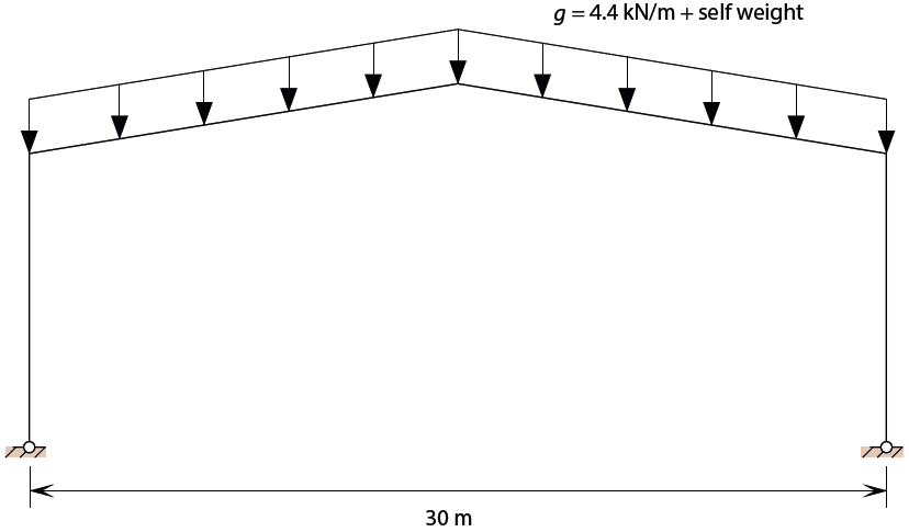
2 |
Roof |
G (Permanent) |
4,4 kN/m |
3 |
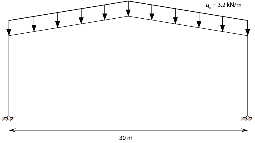
Snow |
S (Variable) |
3,2 kN/m |
4 |
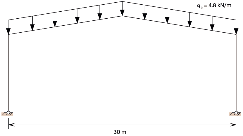
Imposed |
Q (Variable) |
4,8 kN/m |
5 |
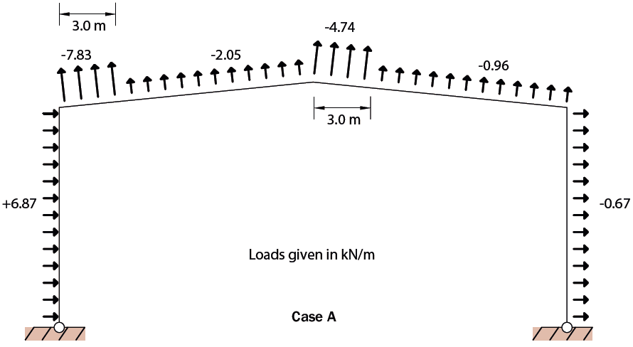
Wind |
W (Variable) |
See figure below |
7 |
Imperfection |
IMP (Imperfection) |
Sway 19 mm (1/689), bow 1/300 (stress-free) |
Loadcase 2 - Roof
Loadcase 3 - Snow
Loadcase 4 - Imposed
Loadcase 5 - Wind
See also
A detailed description regarding the topic Imperfections you will find in the tutorial Imperfection Concept.
Load combinations
Number |
Title |
Permanent |
Leading Variable |
Accompanying Variable |
|---|---|---|---|---|
1001 |
1.35G+1.35G+1.5·Q+IMP |
1.35 |
Imposed 1.5 |
|
1002 |
1.35·G+1.35·G+1.5·S+0.75·W+IMP |
1.35 |
Snow 1.5 |
Wind 1.5·0.5 |
1003 |
1.35·G+1.35·G+0.75·S+1.5·W+IMP |
1.35 |
Wind 1.5 |
Snow 1.5·0.5 |
1004 |
G+G+1.5·W+IMP |
1.0 |
Wind 1.5 |
Workflow: step by step
Start a new project - define materials and cross-sections
Title: Materials and cross-sections | Quality: 1080p Full HD | Captions: English
Hint
Two stress points of the same name are necessary for c/t check, which later will be done at the chapter Resistance of cross-sections. The stress points are automatically generated for standard cross-sections.
In this example the haunches have been generated by using the linear interpolation between two master cross-sections. In case you need parametric defined haunches then you may also use the CABD feature. This requires a CABD license.
Generate system and loads inside SOFiPLUS
Title: System and loads | Quality: 1080p HD | Captions: English
As already mentioned in chapter “Load combinations”, we create 4 load combinations:
Note
If you are going to run a 2nd Order Analysis, then you need to calculate every load combination separately, i.e. superposition principle is not valid any more. Therefore the tasks “Loadcase Combination Manager” and “Analysis of Combined Loadcases” are used in the “standard” steel-design workflow.
Note
According to the reference paper, a 2nd Order Analysis should be done, because the analysed frame is sensitive to 2nd order effects. The principle of an imperfection is, that this phenomenon should not create itself any additional stresses, i.e. the imperfection is stress-free.Additional stresses are created only due to the fact that other loads are acting on an imperfect structure. Thus, the commonly used Equivalent Horizontal Force (EHF) method is generally incorrect. We use a stress-free imperfection, which is the more appropriate and correct method of analysis.
See also
Detailed description of automatic generation of load combinations using the task “Loadcase Combination Manager” which can be found in the tutorial Imperfection Concept.
Analysis and design
Title: Analysis and design | Quality: 1080p HD | Captions: English

Results
Title: Results | Quality: 1080p HD | Captions: English