Import Axis - Supported Formats#
Depending on the file format, various additional settings are displayed in the Axis Import dialog, accuracy differs and some additional options are added or disabled. Please read carefully the information below of the supported formats.
LandXML#
LandXML formats consists of Alignment and Profile definition. This information will be translated accordingly to Horizontal and Vertical alignment. One Alignment in LandXML file may have more then one Profiles assigned. In this case you need to select in the SOFiSTiK: Axis Import Dialog, which Profile should be imported.
You are also able to create an axis from PlanFeature (feature lines in Autodesk Civil3D). Axis will be created as polycurve and the geometry will not be accesible through the Axis dialog.
Land XML files have bigger accuracy (eight decimal places) as in SOFiSTiK Bridge Modeler (four decimal places). Becuase of that, there might be some inaccuracy at the end of the axis. In case the difference exceeds the defined accuracy in the Accuracy Settings, a corresponding warning will appear.
After importing the axis you can open Axis Dialog using Edit Axis command and modify all axis properties (geometry, placements, variables and secondary axes).
Axis Import dialog for LandXML files.
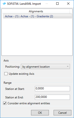
Alignments#
Select alignment and profile defined in LandXML file to import into the project.
Positioning#
Select the coordinates to place the imported axis accordingly.
by alignment location - places the beginning of the axis always at the internal origin
by Project base point - places the axis according to the project coordinates
by Shared site - places the axis according to the shared coordinates
by Internal origin - places the axis according to the internal Revit coordinates
Update existing Axis#
Update existing Axis checkbox enables you to updated previously created or imported axis. If activated, after confirming the import with OK, you need to select an axis. All the other information that were previously defined (like placements, variables, secondary axis) will remain.
Range#
Define ‘Station at Start’ and ‘Station at End’ values in order to import only the specific range of the alignment into Revit. Per default whole alignment will be considered.
If ‘Consider entire alignment entities’ checkbox is activated, the range of the axis will be imported with entire first and last alignment element in defined range. Created axis may exceed previously defined range.
Warning
Disactivating this checkbox will cause generation of new alignment elements. Start and End Station of created axis will be as defined in the range. However, this process may cause inaccuracies.
TRA/GRA#
TRA and GRA formats consists of Alignment and Profile definition. This information will be translated accordingly to Horizontal and Vertical alignment. In order to import both horizontal and vertical alignments, make sure that TRA and GRA file are both in the same folder. In ‘SOFiSTiK: Select Source File’ dialog, select TRA file. GRA file with the same name will be automatically imported as vertical alignment.
After importing the axis you can open Axis Dialog using Edit Axis command and modify all axis properties (geometry, placements, variables and secondary axes).
Axis Import dialog for TRA/GRA files.
Alignments#
Select alignment and profile defined in LandXML file to import into the project.
Positioning#
Select the coordinates to place the imported axis accordingly.
by alignment location - places the beginning of the axis always at the internal origin
by Project base point - places the axis according to the project coordinates
by Shared site - places the axis according to the shared coordinates
by Internal origin - places the axis according to the internal Revit coordinates
Update existing Axis#
Update existing Axis checkbox enables you to updated previously created or imported axis. If activated, after confirming the import with OK, you need to select an axis. All the other information that were previously defined (like placements, variables, secondary axis) will remain.
Range#
Define ‘Station at Start’ and ‘Station at End’ values in order to import only the specific range of the alignment into Revit. Per default whole alignment will be considered.
If ‘Consider entire alignment entities’ checkbox is activated, the range of the axis will be imported with entire first and last alignment element in defined range. Created axis may exceed previously defined range.
Warning
Disactivating this checkbox will cause generation of new alignment elements. Start and End Station of created axis will be as defined in the range. However, this process may cause inaccuracies.
JSON#
You can import only JSON files, which where previously created using Axis Export functionality.
This format consist of axis geometrical definition, placements and variables. After importing the axis, you can modify its properties using Edit Axis command.
CSV / TXT / XYZ#
You can import axis geometry using the points’ coordinates. All the values have to be arranged in the columns and have consistent separators between columns and decimal separator. After importing the axis, you can modify its properties using Edit Axis command. Horizontal and Vertical Alignment sections are not available. If you want to modify the axis’ geometry, you have to import axis again with activated ‘Update existing Axis’ checkbox.
Axis Import dialog for CSV/TXT/XYZ files.
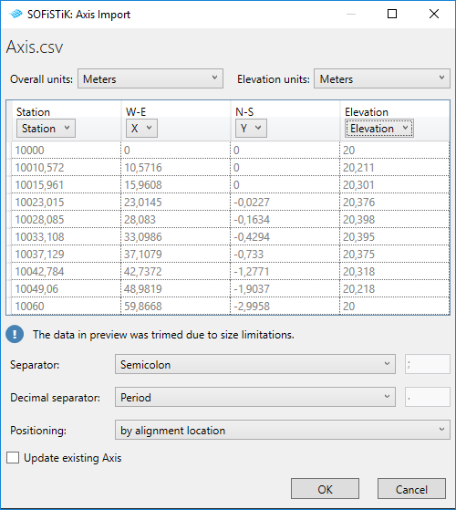
Overall and Elevation units#
Set the unit that has been used to describe the values in the table.
Table#
All of the available columns in the file are shown in the table. You have to assign the columns to the proper coordinates (X/Y/Elevation). You don’t have to assign any column to ‘Station’ property. However, additional information about stationing will increase accuracy and fill in the ‘Station at Start’ value automatically.
Separator#
Select the sign, that is used to separate the columns in the file in order to properly recognise the file structure.
Decimal separator#
Select the decimal separator that is used in the file in order to properly interpretate the values.
Positioning#
Select the coordinates to place the imported axis accordingly.
by alignment location - places the beginning of the axis always at the internal origin
by Project base point - places the axis according to the project coordinates
by Shared site - places the axis according to the shared coordinates
by Internal origin - places the axis according to the internal Revit coordinates
Update existing Axis#
Update existing Axis checkbox enables you to updated previously created or imported axis. If activated, after confirming the import with OK, you need to select an axis. All the other information that were previously defined (like placements, variables, secondary axis) will remain.
Note
Generated Axis using interpolation points assure exact position of the axis only in the position of the points. The curve will be interpolated between them and may differ from the curve, that was used to generate the points.
CDB#
CDB files contain axis definition of SOFiSTiK project, axis alignment, placement and variables. You can use it to generate geometrical model of the bridge. After importing the axis, you can modify its properties using Edit Axis command.
Axis Import dialog for CDB files.
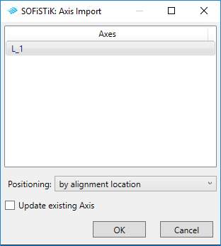
Positioning#
Select the coordinates to place the imported axis accordingly.
by alignment location - places the beginning of the axis always at the internal origin
by Project base point - places the axis according to the project coordinates
by Shared site - places the axis according to the shared coordinates
by Internal origin - places the axis according to the internal Revit coordinates
Update existing Axis#
Update existing Axis checkbox enables you to updated previously created or imported axis. If activated, after confirming the import with OK, you need to select an axis. All the other information that were previously defined (like placements, variables, secondary axis) will remain.