Elevation Points#
Creates a sketch of component’s profile and a table with elevation points along an axis. You can choose individually which points should be annotated by activating the proper checkbox in dialog. You can choose among the points of profile (vertexes) or reference points in the profile family that have name.
Click SOFiSTiK Bridge tab
 Shop Drawings panel
  (Elevation Points)
Select a Component
SOFiSTiK: Elevation Points dialog displays.
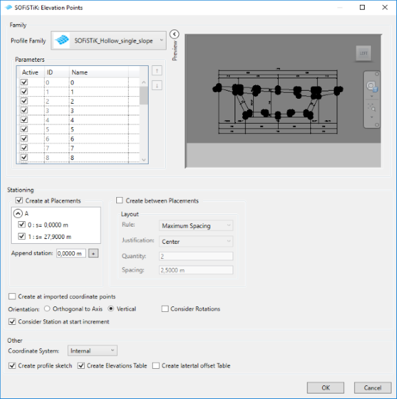
Activate points to annotated, select stationing, orientation and rotation of stations.
Select coordinate system and choose which tables will be created and confirm with OK.
Drafting view and Revit Schedules with selected tables are created and opened.
Layout items#
Create at Placements - select placements to create elements at their positions
Create between Placements - if activated, elements will be created between the selected placements according to the chosen layout rule
Orientation: Orthogaonal to Axis, Vertical - decide the orientation of the placed elements
Consider Rotation - if activated, elements will be rotated according to the placement’s rotation
Apply for each interval - layout rule will be applied for each placement interval (for each two selected neighbouring placements)
Measurement Types#
Curve Parameter - Spacing of the Layout Rule will be calculated according to the stationing of an axis
Chord Length - Spacing of the Layout Rule will be calculated according to the exact defined distance between two points
Projected Chord Length - Spacing of the Layout Rule will be calculated according to the exact defined distance between two points projected on the horizontal surface