Beam Family Customization#
You can use Beam command to place beam components on created Girder Layout.
Beam Families are Adaptive Generic Families (.rfa), which consist of two Adaptive points (‘1’ and ‘2’) that are placed accordingly at the beginning and at the end of each girder. Insertion (adaptive) points and additional family parameters control the geometry of the beams. Adaptive point ‘1’ has to be placed in the family’s origin and adaptive point ‘2’
Here you can find tips how to create and parametrize Beam Family.
Basic Geometry#
Here you can find how to create basic geometry of Beam Family
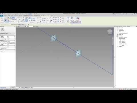
Create two points on horizontal reference level
Make both of the adaptive
Position point ‘1’ in the family’s origin and point ‘2’ on Center (Front/Back) plane (following X axis).
Select both points and use tool ‘Spline through points’ - created line will be controlled by adaptive points
Select line and activate ‘Is Reference Line’ checkbox in properties Palette
Place reference point on reference line
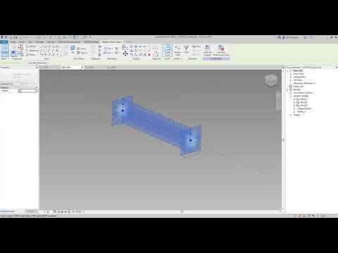
Define Beam Profile in separate family and load into Beam Family.
Place Beam Profile on reference point or sketch a profile on vertical plane of reference point.
Select reference line and profile and create Solid Form using Create Form functionality.
Variable Cross Section#
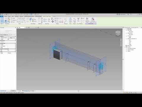
You can create Beam with variable cross section by placing two or more profiles on the reference line. You can parametrize the profile and modify its parameters in Beam Families to increase efficiency.
Create reference line with reference points according to Basic Geometry paragraph.
Place the Beam Profile on reference point or sketch profile on vertical planes of reference point.
Depending on the variability, one (continous geometry) or more (sharp edge) solids are created. (see note below)
In order to control the position of the profiles, select reference point and set Dimensions parameters in Properties Palette.
Note
Creating form with two profiles results in geometry with linear interpolation. By creating solids with 3 or more profiles you’ll obtain geometry with the spline form.
Different Cross Section#
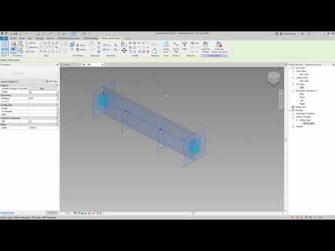
Create reference line with reference points according to Basic Geometry paragraph.
Load two or more Beam Profiles in Beam Family.
Place Beam Profiles on reference points or sketch profiles on vertical planes of reference points.
Create Solid using form functionality between two profiles.
In case solid is created using two different Beam Profiles, make sure, that the number of contour lines is equal.
Rotation#
Create reference line with reference points according to Basic Geometry paragraph.
Place the Beam Profile on reference point or sketch profile on vertical plane of reference point
Rotate the Profile using Rotation parameter of Reference Point.
Connect the Rotation Parameter of Reference Point to the family instance Parameter to control the beam’s rotation in the project.
Skewed Geometry#
In order to create skewed elements, you need to rotate profiles or cut geometry using Void Forms. Profile rotation will cause changes in beams cross section. Therefore, recommended workflow is using Void Forms. Beam’s Solid Form has to be longer then reference line and Void element has to be controlled by the reference point’s rotation parameter.
Create reference line with reference points according to Basic Geometry paragraph. Name points ‘Ref_1’ and ‘Ref_2’
Create Reference point on ‘horizontal plane’ of Ref_1 and Ref_2 points. Name new points ‘Void_Inner_1’ and ‘… 2’
Set rotation parameter to control the skew angle in the Family Properties Palette.
You can temporary set an offset parameter. It will help you to distinguish between planes of reference points, which are at the same position.
Create Reference points on ‘vertical plane’ (orthogonal to reference line) of Ref_1 and Ref_2 points. Name new points ‘Beam_Profile_1’ and ‘’Beam_Profile_2’
Set an offset parameter so that new point goes outside of the reference line.
Create Reference points on ‘vertical plane’ (orthogonal to reference line) of ‘Beam_Profile_1’ and ‘…_2’ points. Name new points ‘Void_Outer_1’ and ‘…2’
Set an offset parameter to position the point further from reference line.
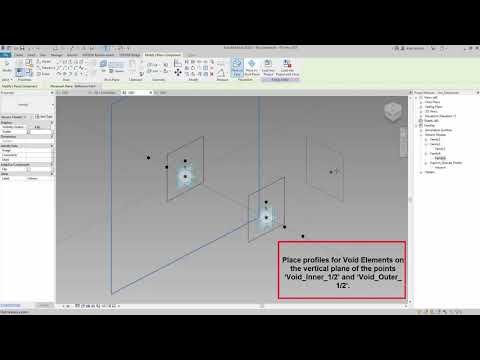
Place profiles for Void Elements on ‘Void_Inner_1/2’ and ‘Void_Outer_1/2’ points or sketch profiles on their horizontal plane.
Create Void Forms using profiles on Void_Inner_1/2 and Void_Outer_1/2 points.
Place profiles for Beam Elements on ‘Beam_Profile_1/2’ points or sketch profiles on their horizontal plane.
Create Solid Forms using profiles on Beam_Profile_1/2 points.
Cut Solid Form geometry with Void Form geometry using Cut functionality.
Deactivate visibility of the Solid and Void Form profiles
Openings#
By following these rules you can create any geometry you want.
Beam Families are Adaptive Generic Families (.rfa), which consist of two Adaptive points (‘1’ and ‘2’) that are placed accordingly at the beginning and at the end of each girder. Insertion (adaptive) points control the geometry of the beams.
You can find some types of beam families in the installation directory.
C:\ProgramData\Autodesk\ApplicationPlugins\sofistik_bridge_modeler_20XX.bundle\Contents\data
You can use already prepared Revit Families, customize them or create your own ones.
Beam Profile#
You can create and parametrize beam’s geometry by creating profiles in separate Generic Family. Connect Profile Family parameters with Beam Family parameters to control the geometry and create types.
Place Adaptive Point in the Family origin
Model closed chain of lines on the horizontal plane of Adaptive Point.
Load Profile Family into Beam Family
Parametrization#
You can sketch lines and parametrize them with dimensions. Alternatively, create line using Spline Through Points functionality and control distance with Point’s Offset Parameter
By Dimensions: * Sketch lines on horizontal plane of Adaptive Point * Place dimensions between lines/reference planes * Connect Dimensions with Family Parameters (use instance parameters)
By Offset Parameter (Points): * Place Point with reference to Adaptive Point * Place another point on selected plane of first point. * Set Offset parameter of secong point (point will move in orthogonal direction to the plane it has been placed on) * Select two points * Use Spline Through Points functionality to create line
Orientation#
You can place the Profile Family on the point that has reference to Adaptive Point or to Reference Line. Therefore, please note that the orientation of Profile changes accoriding to the host element.
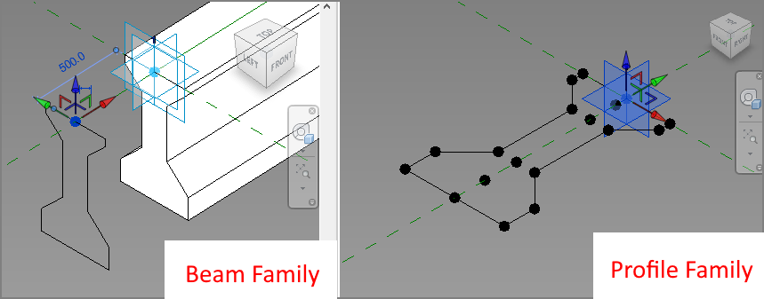
Reference Point hosted by Adaptive Point
‘Z’ coordinate of Adaptive Point in Profile Family will be mapped with ‘X’ coordinate of Reference point hosted by Adaptive Point. ‘X’ coordinate of Adaptive Point in Profile Family will be mapped with ‘Y’ coordinate of Reference point hosted by Adaptive Point. See picture below
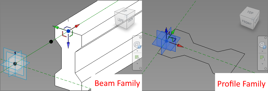
Reference Point hosted by Reference Line
‘Z’ coordinate of Adaptive Point in Profile Family will be mapped with ‘X’ coordinate of Reference point hosted by Reference Line. ‘X’ coordinate of Adaptive Point in Profile Family will be mapped with ‘Z’ coordinate of Reference point hosted by Reference Line. See picture below
Beam Types#
You can create different Types of the same Beam Family and select Type while placing Beams on Girder Layout.
Recommended workflow:
Create a Beam Profile Family and parametrize it with Instance Parameters.
Note
Please note how the profile is oriented in the family. While placing the profil on reference line or reference point hosted on ref. plane, the profile orientation may differ. Please check Beam Profile paragraph for more information.
Load a Profile Family into a Beam Family.
Create a set of family parameters, that control the beams geometry - Type Parameters.
Place a profile on the reference line or reference point
Select profile and assign Profile Parameters to Family (Beam) Parameters
Create types of Beam Family and fill the parameters with the proper values
Create Solid Form