Combine Loads#
Using the SSD task ![]() ‘’Combine Loads’’,
the required load case combinations which are necessary for a specific design task can be defined manually for all members or automatically for beam structures or columns.
‘’Combine Loads’’,
the required load case combinations which are necessary for a specific design task can be defined manually for all members or automatically for beam structures or columns.
Tab Combinations#
When opening a new task ‘’Combine Loads’’ no load case combinations are shown.
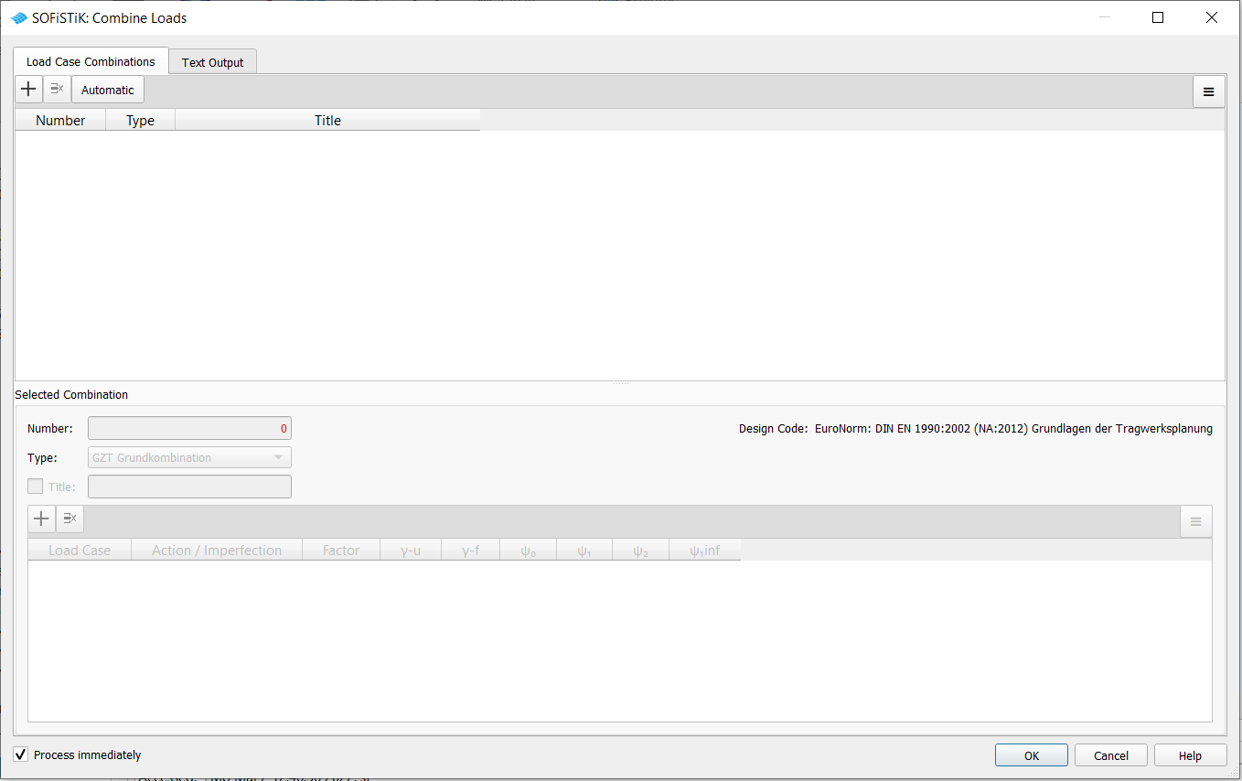
Now you have two possiblities to generate load case combinations:
a manual definition
With a click on the button + a new Number is generated and you can define the load case combination as wished in the lower part at Selected Combination.
an automatic generation
If beam members or columns are availalbe in the system, it is possible to generate the load case combinations automatically by clicking on the button Automatic.
Note
The automatic generation of load case combinations is only possible using action combinations which are available in the database.
The action combinations can be available as default for the corresponding design code for buildings (INI file) or as manually defined action combinations in the task “Combination Rules” e.g. for design codes for bridges.
Manual Definition#
The load case combination is put together at Selected Combination in the lower part.
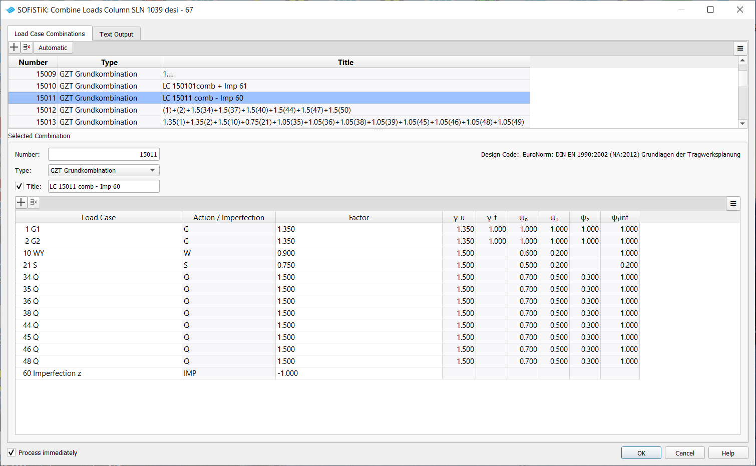
At first the load case combination number has to be defined at Number.
At Type the selection for the further use of the combination is choosen. This selection is decisive for the subsequent design tasks.
The title of the load case combination is generated automatically taking into account the load cases and their factors. The title can be modified manually by setting the tick.
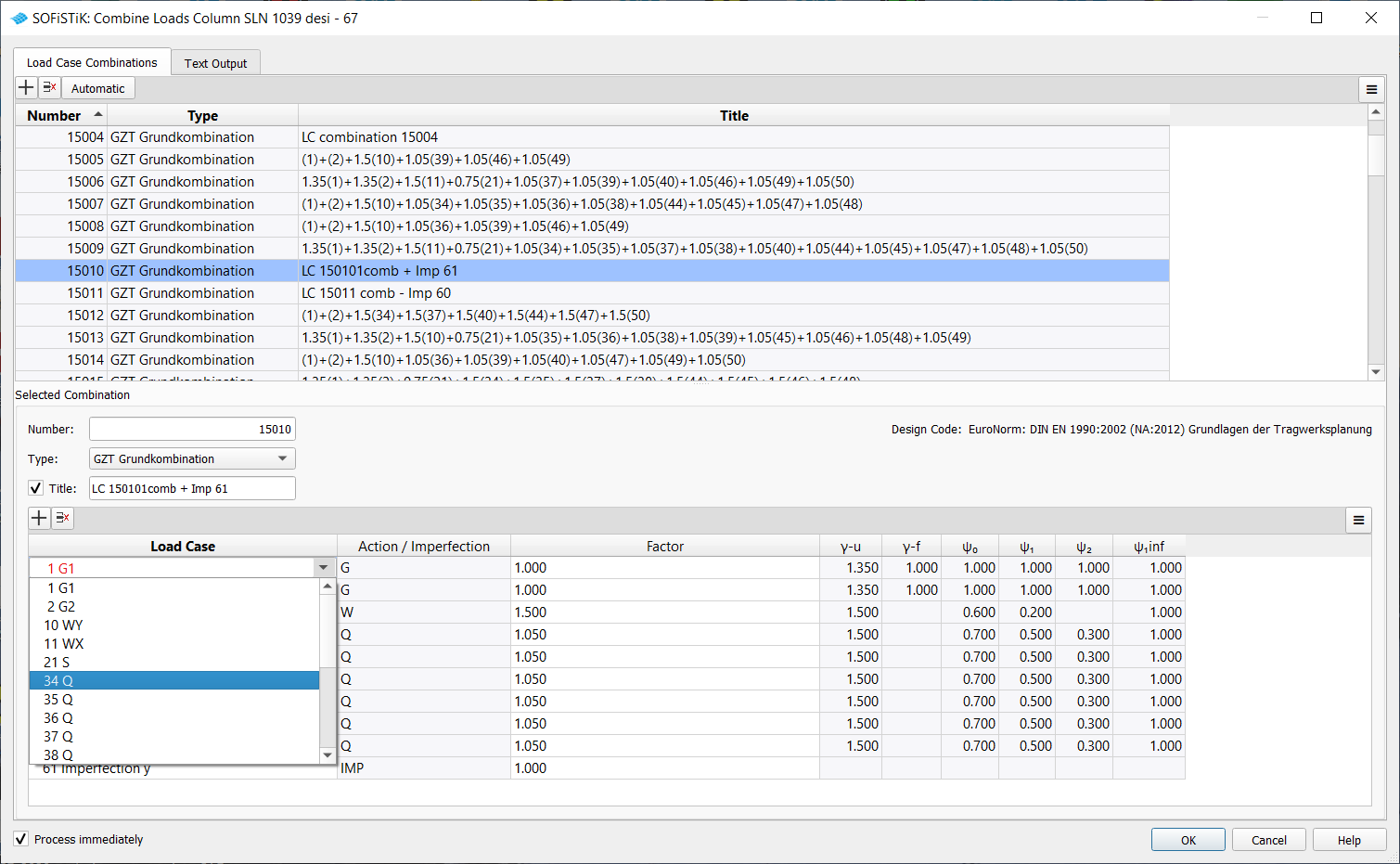
In the table the single load cases can be added with their factors. Load cases can be added using the button + for a new load case. With a click on the corresponding load case in the table a combobox is opened. The load case numbers can be changed here.
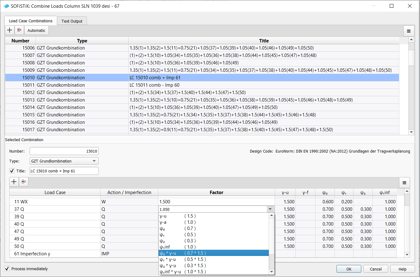
In the column Factor the factor can be input directly as number. A factor with a “-” is also possible for the direction selection of load cases from earthquake analysis or for imperfection load cases. Or you can use the safety factors, the combination coefficients, consequences class factor and reduction factors as well as their products using the combobox functionallity. The information in the columns Action/Imperfection and of the saftey factors and combination coefficients serves as an overview and shows the values of the database.
Automatic Generation#
Clicking on the Automatic button, a subdialog is opened for the necessary information in order to generate automatically the load case combinations using the action combinations.
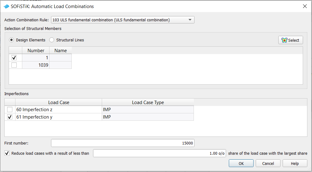
Action Combination Rule
At first it is necessary to select an action combination which is defined either for the corresponding design code in the database (INI file) or in the task “Combination Rules” or an MAXIMA input.
Hint
If safety factors or combination coefficients of an action have been temporarily changed in the task “Combination Rules”, this is not taken into account here, as this change is not stored in the CDB.
Selection of Structural Members
In the second step a structural member of beams should be selected either as design element or structural line.
Hint
The automatic generation of load case combinations is only useful for one beam member or column to overwiew the determined load case combinations.
Imperfections
If one or more imperfection load cases exist, then it is possible to add them with the factor 1 to the generated load case combinations.
Hint
The factor can be changed to -1 for the other direction of the imperfection in the main dialog at Selected Combination.
First Number
Input of the first load case number for the resulting load case combinations
Reduction of the used variable load cases that make only a very small contribution
With a tick and a percantage value variable load cases that make only a very small contribution in a load case combination are not considered.
Note
The permament load cases are considered in any case. That means, a permanent load case for an additional dead load is attached even if it has no influence on the specific member. This is the case, for example, for multi-storey columns and additional dead load in the basements. Here the corresponding normal forces on the upper floors are zero for an structural engineer, however, in the cdbase it is a very small value.
Hint
For a structural member in the overall system, a reduction leads to a better overview of the determined load case combinations. The number of variable load cases used for a load case combination can thus be reduced.
Attention
Using the reduction possibility for all components of an overall system can lead to more load case combinations. The investigation is always carried out on member sections, whereby, for example, a load case can be omitted in one member section but used in the adjacent member section. This then leads to two load combinations.
The determined load case combinations are given sorted according to their frequency.
Internal procedure#
In an internal procedure the progam MAXIMA runs and the determined load case combinations are searched and indicated in the dialog.
Especially in the case of bending with normal force or biaxial bending, the load case combinations for the decisive stresses of the beam member or column should be found correctly. In addition to the internal forces and moments, the normal stress in specific stress points of the cross section is also used as superposition value. Since there are usually no stress points defined in the cross section, the program forms an enveloping square around the cross-section and defines a controllable number of stress points on the diagonal.

The stress points inside the cross section are especially necessary for the calculation according to the second order theory, since load combinations with a high normal forces are often decisive here.
The founded combinations are sorted by frequency so that the combination with the largest counter is at the top.
Hint
A detailed description of this internal procedure is available in our Online Tutorial https://www.sofistik.de/documentation/2023/en/tutorials/superpositions/bb14-bockhold-vossen/superposition_bb14-bockhold-vossen.html
Corresponding Program#
As a result, an input for the program SOFiLOAD is generated, e.g.
PROG SOFiLOAD
HEAD Combine loads

LC NO 15010 TYPE (D)  TITL "LC 15010 comb + Imp 61"
COPY NO 1 FACT 1
COPY NO 2 FACT 1
COPY NO 11 FACT 1.5
COPY NO 37 FACT 1.05
COPY NO 39 FACT 1.05
COPY NO 40 FACT 1.05
COPY NO 47 FACT 1.05
COPY NO 49 FACT 1.05
COPY NO 50 FACT 1.05
COPY NO 61 FACT 1

LC NO 15011 TYPE (D)  TITL "LC 15011 comb - Imp 60"
COPY NO 1 FACT 1.35
COPY NO 2 FACT 1.35
COPY NO 10 FACT 0.9
COPY NO 21 FACT 0.75
COPY NO 34 FACT 1.5
COPY NO 35 FACT 1.5
COPY NO 36 FACT 1.5
COPY NO 38 FACT 1.5
COPY NO 44 FACT 1.5
COPY NO 45 FACT 1.5
COPY NO 46 FACT 1.5
COPY NO 48 FACT 1.5
COPY NO 60 FACT -1

LC NO 15012 TYPE (D)  TITL "(1)+(2)+1.5(34)+1.5(37)+1.5(40)+1.5(44)+1.5(47)+1.5(50)"
COPY NO 1 FACT 1
COPY NO 2 FACT 1
COPY NO 34 FACT 1.5
COPY NO 37 FACT 1.5
COPY NO 40 FACT 1.5
COPY NO 44 FACT 1.5
COPY NO 47 FACT 1.5
COPY NO 50 FACT 1.5

END