Design parameters of area elements#
The SSD task ![]() ‘’Design parameters of area elements’’
contains the following tabs:
‘’Design parameters of area elements’’
contains the following tabs:
Common
Graphical Output
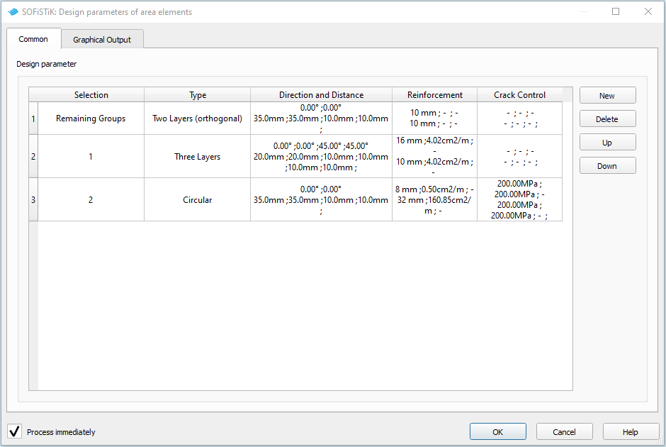
Common#
You can define different design parameters for different area elements groups. The first row is the default definition for all remaining groups for which no extra definitions were made. You can add, delete and sort definition rows with the commands on the right.
The following parameters can be defined:
(Group) Selection
(Reinforcement) Type
Direction and Distance
Reinforcement
Crack Control
Selection#
In the Group Selection dialog, you can either select primary or secondary groups from a list or
graphically in the ![]() Animator.
Animator.
Type#
Either you deselect a group of area elements for the design by selecting ‘No design’. Or you can choose from four different types of reinforcement:
Two Layers (orthogonal)
Two Layers
Three Layers
Circular
Direction and Distance#
The direction of and distance between the rebars of each layer can be defined individually for the upper reinforcement mesh (support reinforcement) and the lower reinforcement mesh (span reinforcement).
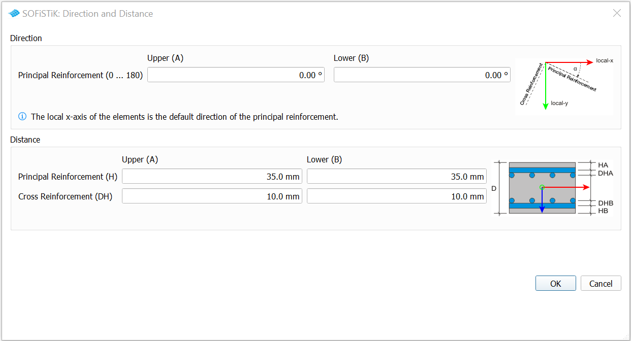
Depending on the selected type, you can define angles for either * only the principal reinforcement (the cross reinforcement lies orthogonal), * the principal and a second cross reinforcement layer, * the principal and two additional reinforcement layers, * or the meridian angle, the descent angle and the midpoint for circular reinforcements.
Important
The direction values describe the angles between the local x-axis and the particular reinforcement. They are positive in the clockwise direction. Thus, the default direction for the principal reinforcement is the direction of the local x-axis!
Note
The distance values for the principal reinforcement (H) describe the centre distance from the upper/lower plate edge. The distance values for the cross and third layer reinforcement (DH and DDH) describe the centre distance to the principal reinforcement.
Reinforcement#
In the Reinforcement dialog, diameters can be selected separately for each reinforcement layer of the
upper mesh and lower mesh respectively. In addition to the diameter, a
minimal or maximal reinforcement can be defined. You can enter own values or
use the ![]() Reinforcement Calculator
to calculate the relativ reinforcement values based on the diameter and the number
of or distance between the rebars.
Reinforcement Calculator
to calculate the relativ reinforcement values based on the diameter and the number
of or distance between the rebars.
Crack Control#
For each layer of the upper or lower reinforcement mesh, the parameters ‘Crack width’ and ‘Steel stress’
can be defined. These definitions are required for the crack width check in
the task ![]() Design SLS (Area Elements).
Design SLS (Area Elements).
The permissible crack width is used for the crack with control with direct calculation acc. to EN 1992-1-1, 7.3.3 or without direct calculation acc. to EN 1992-1-1, 7.3.4. If you want to check the crack width control acc. to EN 1992-1-1. table 7.3N, a steel stress value must be selected.
Graphical Output#
The tab “Graphical Output” is a common tab that appears in many SSD tasks. It is used to
plot the predefined results by using the program ![]() Graphic.
Graphic.
Depending on the type of the task, different predefined results will be provided for the selection.
To deactivate the plotting of graphics, just uncheck all checkboxes
![]()
![]() .
.