Design SLS (Area Elements)#
The SSD task ![]() ‘’Design SLS (Area Elements)’’
contains the following tabs:
‘’Design SLS (Area Elements)’’
contains the following tabs:
General
Quad Elements
Control Parameter
Text Output
Graphical Output
General#
For the design in the serviceability limit state, a designcase from previous design steps can be set as minimum. After the design, the reinforcement from the SLS design is compared to the reinforcement from the selected minimum design case and only the maximal values are stored under the designcase number entered at ‘Designcase SLS’.
In the loadcase selection table you can find all loadcases generated in the
![]() Superpositioning for Combination Rules task with types suitable for the SLS design.
You can select loadcases manually or select a group of loadcases by type, namely:
Superpositioning for Combination Rules task with types suitable for the SLS design.
You can select loadcases manually or select a group of loadcases by type, namely:
all characteristic loads (type (R)),
all frequent loads (type (F)),
all quasi-permanent loads (type (P)),
all non-frequent loads (type (N)).
Quad Elements#
The main purpose of the Design SLS (Area elements) task is the Crack Width Control acc. to EN 1992-1-1. You can choose between:
Crack Width Control without direct calculation (EN 1992-1-1,7.3.3) or
Direct Calculation of crack width (EN 1992-1-1, 7.3.4).
Crack Width Control without direct calculation#
The check limits the available steel stress in the serviceability state to a permissible value.
If a permissible steel stress has been entered for the Crack Control in
the ![]() Design parameters of area elements task,
this value is taken. You can use his workflow to check the crack width acc.
to EN 1992-1-1. table 7.3N.
If no permissible steel stress has been defined, the value comes from a code
depending table based on the bar diameter.
Design parameters of area elements task,
this value is taken. You can use his workflow to check the crack width acc.
to EN 1992-1-1. table 7.3N.
If no permissible steel stress has been defined, the value comes from a code
depending table based on the bar diameter.
Direct Calculation of crack width#
If the simple check according to the tables is not sufficing, a direct calculation can occur.
The direct calculated value is checked against the permissible steel stress
defined in the ![]() Design parameters of area elements.
For EN codes also equation 7.14 of EN 1992-1-
1 7.3.4(3) is taken into account (except Germany and Austria). If the check is
not explicitly programmed for a specific code, the check is done based on Eurocode.
For this please check the protocol of the design parameters in the output.
Design parameters of area elements.
For EN codes also equation 7.14 of EN 1992-1-
1 7.3.4(3) is taken into account (except Germany and Austria). If the check is
not explicitly programmed for a specific code, the check is done based on Eurocode.
For this please check the protocol of the design parameters in the output.
Hint
For more information on the Crack Width Control with and without Direct Calculation, please see the BEMESS manual.
Control Parameter#
Design Procedure#
You can chose between the Design According to Baumann or the Layer Design. The default setting is the Layer Design.
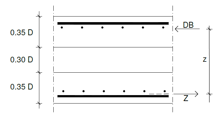
The Design According to Baumann is based on the method described by Baumann (Der Bauingenieur 47 (1972), pages 367-377). It looks a little bit similar to the sandwich-modell of EN-1992-2 annex LL. The moments mxx, myy and mxy as well as the membrane forces nxx, nyy and nxy are converted to effective membrane forces Ax, Ay, and Axy, acting on fictitious disks with a thickness of 0.35 construction element thickness at the outer shell side, see figure.
In the Layer Design the 6 strain parameter (3 strains and 3 curvatures) are calculated iteratively to achieve equilibrium between the 6 inner forces and the 6 external forces nx,ny,nxy,mx,my,mxy. Thereby nonlinear work laws are taken into account for concrete and steel. Inside the reinforcement area no concrete stress is applied.
As all components are taken into account using the strain and curvature tensor, also the compatibility is observed as in the Baumann design. So a tension force acting under 45 degree on a reinforcement mesh causes a necessary compression strut in the concrete.
Hint
For more detailed information on the design procedure according to Baumann or the Layer Design, please take a look at the BEMESS manual.
Area Design#
You can decide, if additional design codes, like the German DIN Fachberichte should be considered for the area design or not.
Text Output#
In the text output task, the extent of the ![]() Report Browser can be controlled. You can choose between:
Report Browser can be controlled. You can choose between:
no text output,
the full text output or
you can manually control the output.
For the manually controlled output you can select the output extend for each output part individually in the control table. On the left, you can see the different output parts. On the right, you can select one of the following options:
default output,
no output,
normal output,
full output or
extensive output.
Graphical Output#
The tab “Graphical Output” is a common tab that appears in many SSD tasks. It is used to
plot the predefined results by using the program ![]() Graphic.
Graphic.
Depending on the type of the task, different predefined results will be provided for the selection.
To deactivate the plotting of graphics, just uncheck all checkboxes
![]()
![]() .
.