Design ULS (Area Elements)#
The SSD task ![]() ‘’Design ULS (Area Elements)’’
contains the following tabs:
‘’Design ULS (Area Elements)’’
contains the following tabs:
General
Shear Reinforcement
Control Parameter
Text Output
Graphical Output
General#
General settings for the design include the definition of a design case number in which the reinforcement will be stored for postprocessing purposes, the possibility to change the Partial Safety Factors for concrete and steel and the selection of loadcases.
In the loadcase selection table you can find all loadcases generated in the
![]() Superpositioning for Combination Rules task with
ultimate limit loads (usually type (D)).
Loadcases marked in the column Punc. include area element bedding and supporting
forces required for punching checks.
Superpositioning for Combination Rules task with
ultimate limit loads (usually type (D)).
Loadcases marked in the column Punc. include area element bedding and supporting
forces required for punching checks.
Note
If no loadcases with area element bedding and supporting forces are selected, no
punching checks will be done. If no loadcases marked for punching are available, please check
your settings in the ![]() Superpositioning for Combination Rules task!
Superpositioning for Combination Rules task!
Shear Reinforcement#
Per default, the compression strut angle theta is calculated automatically according to the chosen design code. Alternatively, you can enter an lower limit for theta. (Higher values are not permitted.)
Note
If you chose to consider an offset value for the shift-rule for tension reinforcement, please check for effects following the manual input of a lower limit for theta.
For the punching checks, you can choose between three options:
Check punching and increase the main reinforcement if necessary,
Just check punching, but do NOT increase the main reinforcement or
Do no punching checks.
Hint
If you want to deselect individual nodes for the design, use a separate
![]() Text Editor task in front of the design task with input
PUNC no. HEAD OFF. For more information, please see the BEMESS manual.
Text Editor task in front of the design task with input
PUNC no. HEAD OFF. For more information, please see the BEMESS manual.
Punching Checks#
Punching Checks are performed with the maximum support reaction. If no support reaction is found or the shear stress is too low, no punching check occurs.
Note
Punching checks require loadcases with area element bedding and supporting forces. Please make sure these loadcases are selected in the General tab.
You can enter a value for the maximum bending reinforcement ratio RO_V due to shear in the punching area. If a design without shear reinforcement would require a higher bending reinforcement than RO_V, the design process switches to the check with shear reinforcement.
Additionally, you can enter a second maximum bending reinforcement ratio RO_V, which applies to checks outside the punching area.
Control Parameter#
Design Procedure#
You can chose between the Design According to Baumann or the Layer Design. The default setting is the Layer Design.
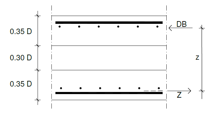
The Design According to Baumann is based on the method described by Baumann (Der Bauingenieur 47 (1972), pages 367-377). It looks a little bit similar to the sandwich-modell of EN-1992-2 annex LL. The moments mxx, myy and mxy as well as the membrane forces nxx, nyy and nxy are converted to effective membrane forces Ax, Ay, and Axy, acting on fictitious disks with a thickness of 0.35 construction element thickness at the outer shell side, see figure.
In the Layer Design the 6 strain parameter (3 strains and 3 curvatures) are calculated iteratively to achieve equilibrium between the 6 inner forces and the 6 external forces nx,ny,nxy,mx,my,mxy. Thereby nonlinear work laws are taken into account for concrete and steel. Inside the reinforcement area no concrete stress is applied.
As all components are taken into account using the strain and curvature tensor, also the compatibility is observed as in the Baumann design. So a tension force acting under 45 degree on a reinforcement mesh causes a necessary compression strut in the concrete.
Hint
For more detailed information on the design procedure according to Baumann or the Layer Design, please take a look at the BEMESS manual.
Reduction of the permissible concrete compressive stress at transverse tension#
Per default, the permissible concrete compressive stress is reduced by 25 % in the case of transverse tension. The value comes from a german annex which applies if the cracks are perpendicular to the compression. This is the case for the main forces is a finite element quad.
Or you can enter your own reduction value in [%].
Compression failure method for shells and disks#
If the failure method for the ULS design is set to ‘Automatic’, a mechanical correct analysis will be done for possible compression reinforcement. If the principal compressive force can not be carried by the concrete alone, the possibility of compression reinforcement must be checked. Compressive forces can only be taken up by reinforcement which lies in small deviation to the principal compressive force. In this case, the transverse reinforcement gets a tensile force which can be interpreted as a splitting force. For the equilibrium of the external loads n:sub:x, n:sub:y, n:sub:xy with the inner forces of the concrete compressive force and the forces in the reinforcement directions it is now necessary, that the concrete compressive force is set a little bit skew (from the compression reinforcement away). Now the concrete compressive force is not in line with the external principal normal force. If the angle reaches 45 degrees between the new concrete compressive force and the principal compression reinforcement, then no further loads can be taken up anymore. Now it is not possible to design the cross section. Then the error message ’Angle between compressive force and compression reinforcement too large’ is printed.
To avoid the error, you can set the failure method to ‘Always transform into compression reinforcement’. The non absorbable concrete compressive force is then fully taken up by reinforcement without further checks of compatibility and it is assumed, that the compressive force of this inserted compression reinforcement is transferred to the neighbouring elements.
Warning
Usually this method proves valid at singular points and at re-entrant corners, but is not possible at free edges!
Hint
For more detailed information, please take a look at the BEMESS manual.
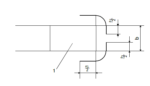
Punching at end of walls#
The punching at wall ends uses a fixed β factor according to the code. At end of walls the side length of the punching perimeter is set to s = a1/ 2 (with limitations according to codes).
With a positive input w in the control parameters, the side length of the design perimeter is set to w * wall thickness.
With a negative input, an additional factor to the side length can be defined:

The default is w = -1.0.
Shear capacity reduction of bubble decks#
Per default, the shear capacity of bubble decks is reduced by 0.55. You can enter your own reduction
factor b. The longitudinal reinforcement is taken into
account in shear design. Shear links are not allowed. So the external shear force
VED must be lower than VRD,bubble = 0.55 * VRD,c of
a full section. The output VED / VRD,max then means VED / VRD,bubble and can be checked in ![]() Graphic.
Graphic.
Area Design#
You can decide, if additional design codes, like the German DIN Fachberichte should be considered for the area design or not.
Text Output#
In the text output task, the extent of the ![]() Report Browser can be controlled. You can choose between:
Report Browser can be controlled. You can choose between:
no text output,
the full text output or
you can manually control the output.
For the manually controlled output you can select the output extend for each output part individually in the control table. On the left, you can see the different output parts. On the right, you can select one of the following options:
default output,
no output,
normal output,
full output or
extensive output.
Graphical Output#
The tab “Graphical Output” is a common tab that appears in many SSD tasks. It is used to
plot the predefined results by using the program ![]() Graphic.
Graphic.
Depending on the type of the task, different predefined results will be provided for the selection.
To deactivate the plotting of graphics, just uncheck all checkboxes
![]()
![]() .
.