Capacity Check for Building Cores#
The task offers the possibility to perform a capacity check for building cores.
This chapter of the documentation focuses on the user input with the graphical user interface.
See also
Find out more about the theoretical principles of the capacity check in the respective chapter of this documentation.
General#
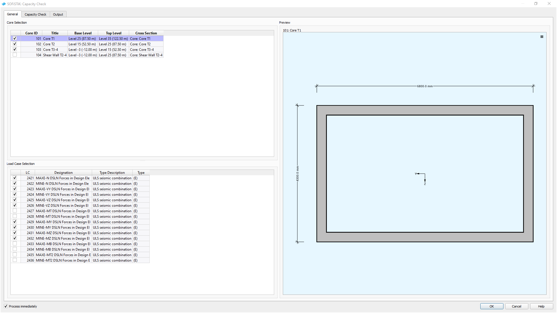
GUI Task Capacity Check for Building Cores - General Tab (click on image to enlarge)#
Core Selection and Preview#
Select the building cores used for the capacity check. On the right a visual aid helps with the identification of the building cores.
See also
Command reference of ![]() SOFiSTiK Analysis + Design for the definition of building cores.
SOFiSTiK Analysis + Design for the definition of building cores.
Load Case Selection#
Select the load cases used in the preliminary design for shear walls. The load case table is filtered for relevant load cases containing design element results. By definition, only load cases for the superpositioning of normal force, shear forces and bending moments are selected, are considered for the design and automatically selected.
The task supports the design combinations listed below. The corresponding worklaws for the material are automatically considered.
(D) |
ULS fundamental combination |
(A) |
ULS accidental combination |
(E) |
ULS seismic combination |
Capacity Check#
Deduces the overall capacity of the building core by comparing the design loads with the resistance values for the cross section. Worklaws for material in the given design limit state and explicit reinforcement distribution of the cross sections are taken into account.
See also
Find out more about the theoretical principles of the capacity check in the respective chapter of this documentation.
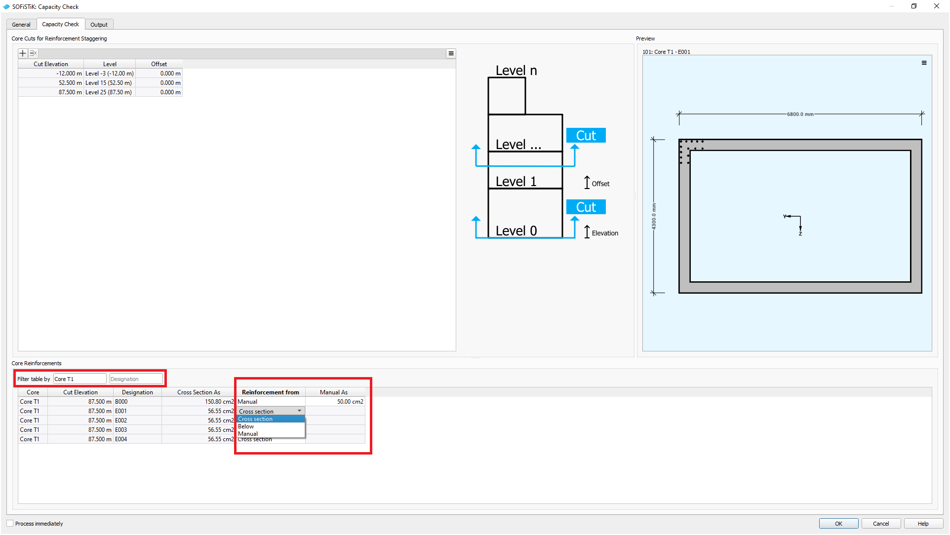
GUI Task Capacity Check for Building Cores - Capacity Check Tab (click on image to enlarge)#
Core Cuts for Reinforcement Staggering#
Define horizontal cuts to introduce reinforcement staggering in your building core cross section.
Note
The definition of reinforcement is done at each cut and valid upwards to the next cut or the end of the core (bottom-up approach).
Preview#
A visual aid to show the cross section and the location of the rebar elements of the building core.
Core Reinforcement#
Adjust the reinforcement amount for a core and thus create a temporary copy of the cross section for the time of calculation. Choose to use the reinforcement amount defined in the cross section editor, link it to the cut below or set a value manually for each designation.
Tip
Use the filters above the table to focus on a specific core and rebar element.
Hint
The initial definition of reinforcement is done in the pre-processor, e.g., ![]() SOFiPLUS(-X) or
SOFiPLUS(-X) or ![]() SOFiSTiK Analysis + Design.
SOFiSTiK Analysis + Design.
Quantity and distance of the rebar elements (single, line, circular or perimetric reinforcement) as well as the location of the individual rebars remain unchanged.
This task offers to scale the reinforcement amount at each location by  .
.