Shear Wall Design#
The task offers the possibility to perform a preliminary design for shear walls.
This chapter of the documentation focuses on the user input with the graphical user interface.
See also
Find out more about the theoretical principles of the shear wall design in the respective chapter of this documentation.
General#
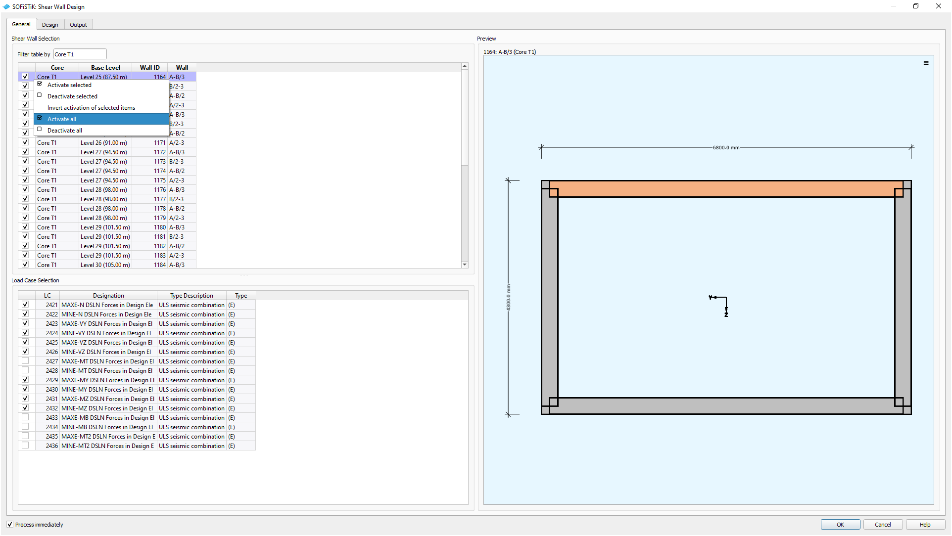
GUI Task Shearwall Design - General Tab (click on image to enlarge)#
Selection of Elements#
Select the walls for the shear design.
Hint
Use the filter above to facilitate the walls associated with a building core
A right-click menu allows to (de-)select all rows at once
See also
Command reference of ![]() SOFiSTiK Analysis + Design for the definition of
building cores.
SOFiSTiK Analysis + Design for the definition of
building cores.
Preview#
Shows the individual shear wall geometry or highlights the wall within the associated building core.
Hint
The coordinate system displayed in the preview represents the local coordinate system of the core cross section.
Load Case Selection#
Select the load cases used in the preliminary design for shear walls. The load case table is filtered for relevant load cases containing design element results. By definition, only load cases for the superpositioning of normal force, shear forces and bending moments, are considered for the design and automatically selected.
The task supports the design combinations listed below. The corresponding worklaws for the material are automatically considered.
(D) |
ULS fundamental combination |
(A) |
ULS accidental combination |
(E) |
ULS seismic combination |
Design#
Offers the possibility to perform a preliminary design for shear walls. The design consists of the components Simplified Compression and Tension Method and Shear Design.
See also
Find out more about the theoretical principles of the design components in the respective chapter of this documentation.
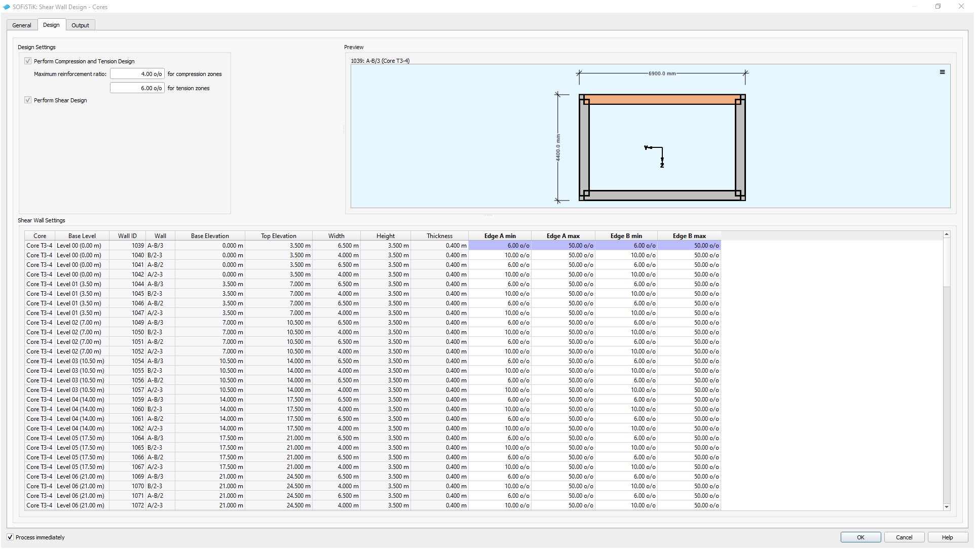
GUI Task Shearwall Design - Design Tab (click on image to enlarge)#
Design Settings#
Set the general design parameters by defining the maximum reinforcement ratio for the individual edge zones.
Preview#
Shows the orientation of the shear wall in the project.
By definition edge zone A is located in positive local z-direction.
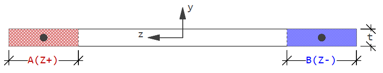
GUI Task Shearwall Design - Edge Zone Definition (click on image to enlarge)#
Shear Wall Settings#
Define the edge zones for each wall by determining the minimum and maximum length for each zone.
Parameter |
Description |
Default |
Range |
|---|---|---|---|
Min |
Minimum length: Starting Point for iteration of simplified compression and tension method |
0 % |
0-50 % |
Max |
Maximum length: End point for iteration of the simplified compression and tension method |
50 % |
0-50 % |
Note
Setting minimum and maximum length to the same value results in a fixed edge zone length.
Hint
It is possible to copy-paste cell values with
CTRL+CandCTRL+VTo copy multiple values, make sure to match ranges for source and target