Section Definition In Json Format#
Format Description#
In this chapter the json format which is used for defining cross sections within the SOFiSTiK Grasshopper Toolkit is described in detail.
Section#
Name |
Type |
Structure |
Description |
|---|---|---|---|
Id |
Integer |
Item |
Id of section |
Name |
Text |
Item |
Name of section |
Unit |
Text |
Item |
Unit of section in which 2d
distances are measured.
Available options are:
“m”, “cm”, “mm”, “ft”, “in”
If nothing is set the selected
Length 3d unit is used
|
MaterialId |
Integer |
Item |
Material number of section.
Materials for different loops can be
set separately
|
Points |
List |
List of section points which make up the geometry of this section |
|
Loops |
List |
List of section loops which define polygonal boundaries of this section |
|
Circles |
List |
List of section circles defining circular boundaries of this section |
|
ThinWalledSegments |
List |
List of thin walled segments defining thin walled section geometry |
|
Variables |
Text / Number |
Map |
Map of variable names and their initial values, this section is depending on |
VariableDescriptions |
Text / Text |
Map |
Optional map of variable names and
a text describing their role inside
the section.
The extended text is separated by a
“:”
“<fullname>:<description>”
|
PointReinforcements |
List |
List of point reinforcements |
|
LineReinforcements |
List |
List of line reinforcements |
|
PerimeterReinforcements |
List |
List of perimeter reinforcements |
|
NonEffectiveZones |
List |
List of non effective zones |
Point#
Name |
Type |
Structure |
Description |
|---|---|---|---|
Id |
Text |
Item |
Identifier of section point |
Coord |
Text |
List |
List with two elements representing
the Y, Z coordinates of a section
point in two-dimensional space.
Available options are:
Expression depending on a set of
variables:
E.g. “0.5*W”
Absolute value:
E.g. 3.2
|
PointType |
Text |
Item |
Type of point describing its role.
For points defined in objects like
section loops or reinforcements the
PointType is given implicitly.
Available options are:
“ConstructionPoint”: default
“StressPoint”
|
Reference |
Text |
List |
List of reference point ids.
Use up to three different reference
points according to reference type.
|
ReferenceType |
Text |
Item |
Type of reference specifying the
frame of reference in which the
coordinates are interpreted.
Available options are:
“euclidean”: If no reference points
are given, the coordinates are
relative to the origin
(0, 0 : default).
If one reference point is specified,
the coordinates are relative to this
point. If two reference points are
given, the Y-coordinate will be
relative to the first reference
point, the Z-coordinate relative to
the second one.
“polar”: Two reference points need to
be specified, with the coordinates
being interpreted in a local frame
whose origin is the first reference
point, first axis is the line between
first and second reference point and
second axis is the line running
through the first point and
perpendicular to the first axis.
“cy”: Three points need to be
sepcified as reference points.
No coordinates are necessary.
The location of the
point will be on a line between the
first and second reference point with
its Y-coordinate being equal to the
Y-coordinate of the third reference
point.
“cz”: Similar to “cy”, but with the
resulting point’s Z-coordinate being
equal to the Z-coordinate of the
third reference point.
|
R |
Text |
Item |
Optional radius specified as
expression or absolute value,
creating a fillet at this section
point.
Only possible for section points
being defined inside a section loop.
|
F |
Text |
Item |
Equivalent to “R” but instead
creating a chamfer at this section
point.
Use either “R” or “F”
|
Loop#
Name |
Type |
Structure |
Description |
|---|---|---|---|
Id |
Text |
Item |
Identifier of section loop |
MaterialId |
Text |
Item |
Material number of section loop |
ConstructionStage |
Text |
Item |
Construction stage of section loop |
Type |
Text |
Item |
Type of section loop specifying if
it is interpreted as an outer
boundary or a inner boundary / hole.
Inner boundaries can also be
specified by setting the MaterialId
to “0”.
Available options are:
“Outer”
“Inner”
|
Points |
List |
List of section points this section loop consists of |
Circle#
Name |
Type |
Structure |
Description |
|---|---|---|---|
Id |
Text |
Item |
Identifier of section circle |
MaterialId |
Text |
Item |
Material number of section circle |
ConstructionStage |
Text |
Item |
Construction stage of section circle |
Type |
Text |
Item |
Type of section circle specifying if
it is interpreted as an outer
boundary or a inner boundary / hole.
Inner boundaries can also be
specified by setting the MaterialId
to “0”.
Available options are:
“Outer”
“Inner”
|
Radius |
Text |
Item |
Radius of circular element as expression or absolute value |
Point |
Item |
Section point where this section circle is located |
ThinWalledSegment#
Name |
Type |
Structure |
Description |
|---|---|---|---|
Id |
Text |
Item |
Identifier of thin walled segment |
MaterialId |
Text |
Item |
Material number of segment |
ConstructionStage |
Text |
Item |
Construction stage of segment |
Type |
Text |
Item |
Type of segment.
Available options are:
“PLAT”: default
“WELD”
|
Thickness |
Text |
Item |
Thickness of segment as expression or absolute value |
PointStart |
Item |
Section point where the start of this segment is located |
|
PointEnd |
Item |
Section point where the end of this segment is located |
PointReinforcement#
Name |
Type |
Structure |
Description |
|---|---|---|---|
Id |
Text |
Item |
Identifier of reinforcement |
Layer |
Text |
Item |
Layer of reinforcement |
MaterialId |
Text |
Item |
Material number of reinforcement |
Diameter |
Text |
Item |
Diameter of reinforcement as expression or absolute value |
TorsionalContribution |
Text |
Item |
Optional torsional contribution.
Available options are:
“PASS”: default
“AKTI”
“ADDI”
Please look up AQUA manual for
further information.
|
Point |
Item |
Section point where this reinforcement is located |
LineReinforcement#
Name |
Type |
Structure |
Description |
|---|---|---|---|
Id |
Text |
Item |
Identifier of reinforcement |
Layer |
Text |
Item |
Layer of reinforcement |
MaterialId |
Text |
Item |
Material number of reinforcement |
Diameter |
Text |
Item |
Diameter of reinforcement as expression or absolute value |
TorsionalContribution |
Text |
Item |
Optional torsional contribution.
Available options are:
“PASS”: default
“AKTI”
“ADDI”
Please look up AQUA manual for
further information.
|
Spacing |
Text |
Item |
Minimal distance between each two single reinforcement bars as expression or absolute value |
BarCount |
Text |
Item |
Total amount of single reinforcement bars as expression or absolute value |
BarDistribution |
Text |
Item |
Optional manner in which bars are
distributed along the line.
Available options are:
“EVEN”: default
“FULL”
“INS”
“ADJA”
“ADJE”
“INSC”
Please look up AQUA manual for
further information.
|
PointStart |
Item |
Section point where the start of this line reinforcement is located |
|
PointEnd |
Item |
Section point where the end of this line reinforcement is located |
PerimeterReinforcement#
Name |
Type |
Structure |
Description |
|---|---|---|---|
Id |
Text |
Item |
Identifier of reinforcement |
Layer |
Text |
Item |
Layer of reinforcement |
MaterialId |
Text |
Item |
Material number of reinforcement |
Diameter |
Text |
Item |
Diameter of reinforcement as expression or absolute value |
TorsionalContribution |
Text |
Item |
Optional torsional contribution.
Available options are:
“PASS”: default
“AKTI”
“ADDI”
Please look up AQUA manual for
further information.
|
Spacing |
Text |
Item |
Minimal distance between each two single reinforcement bars as expression or absolute value |
BarDistribution |
Text |
Item |
Optional manner in which bars are
distributed along the perimeter.
Available options are:
“EVEN”: default
“FULL”
“INS”
“ADJA”
“ADJE”
“INSC”
Please look up AQUA manual for
further information.
|
Inset |
Text |
Item |
Distance between the section loop and this reinforcement as expression or absolute value |
LoopId |
Text |
Item |
Identifier of section loop where this perimeter reinforcement is located |
NonEffectiveZone#
Name |
Type |
Structure |
Description |
|---|---|---|---|
Id |
Text |
Item |
Identifier of non effective zone |
Type |
Text |
Item |
Type of non effective zone.
Detailed explanation can be found in
the AQUA manual.
Available options are a combination
of:
“N”: Normal force
“Y”: Y-ordinate
“Z”: Z-ordinate
“-R”: Reinforcements
“+R”: Reinforcements are active even
if they are in a non effective
part
“V”: Without interpolated vertices
|
Thickness |
Text |
Item |
Thickness of non effectife zone as
expression or absolute value.
If no thickness is specified the
geometry of the zone will be a
two dimensional bounding box
according PointStart, PointEnd.
If thickness has a value the
geometry will be an aligned box from
PointStart to PointEnd with given
thickness
|
PointStart |
Item |
Section point where the start of this zone is located |
|
PointEnd |
Item |
Section point where the end of this zone is located |
Example Sections#
Example Solid Section#
Here is a small example defining a rectangular section in the json format described above.
{
    "Id": 1,
    "Name": "example-section-solid",
    "Unit": "m",
    "MaterialId": 1,
    "Points":
    [
      { "Id": "ORG", "Coord": [ 0.0, 0.0 ] },
      { "Id": "TOP", "Coord": [ 0.0, "-0.5*H" ] },
      { "Id": "BOT", "Coord": [ 0.0, "+0.5*H" ], "PointType": "StressPoint" }
    ],
    "Loops":
    [
      {
        "Id": "L1",
        "Points":
        [
          { "Id": "P1", "Coord": [ "+0.50*W", 0.0 ], "Reference": ["TOP"] },
          { "Id": "P2", "Coord": [ "+0.50*W", 0.0 ], "Reference": ["BOT"], "R": "RO" },
          { "Id": "P3", "Coord": [ "-0.50*W", 0.0 ], "Reference": ["BOT"], "F": "RO" },
          { "Id": "P4", "Coord": [ "-0.50*W", 0.0 ], "Reference": ["TOP"] }
        ]
      }
    ],
    "Circles":
    [
      {
        "Id": "C1",
        "Type": "Inner",
        "Point": { "Id": "PC1",  "Coord":  [ 0.0, 0.0 ], "Reference": [ "ORG" ] },
        "Radius": "RI"
      }
    ],
    "Variables": { "W": 4.0, "H": 3.0, "RI": 0.7, "RO": 0.5, "rfDia": 0.2, "rfSpace": 0.3, "rfInset": 0.5, "rfBDist": 1.0, "nfeY": 2.5, "nfeZ": 2.0 },
    "VariableDescriptions":
    {
      "W":       "Width:Width of Rectagngle",
      "H":       "Height:Height of Rectagnle",
      "RI":      "RadiusCircle:Radius of inner circular element",
      "RO":      "RadiusCorner:Radius at corner points",
      "rfDia":   "DiameterRf:Diameter of reinforcement",
      "rfSpace": "SpacingRf:Spacing of reinforcement",
      "rfInset": "InsetRf:Inset of reinforcement",
      "rfBDist": "BorderDistRf:Border distance of reinforcement",
      "nfeY":    "NeffY:Y coordinate of neff end point",
      "nfeZ":    "NeffZ:Z coordinate of neff end point"
    },
    "LineReinforcements":
    [
      {
        "Id": "RF1",
        "Layer": "1",
        "MaterialId": "2",
        "Diameter": "rfDia",
        "BarDistribution": "FULL",
        "Spacing": "rfSpace",
        "PointStart": { "Id": "RFP1", "Coord": [ "rfBDist", "+rfInset" ], "Reference": [ "P2", "P3" ], "ReferenceType": "Polar"},
        "PointEnd":   { "Id": "RFP2", "Coord": [ "rfBDist", "-rfInset" ], "Reference": [ "P3", "P2" ], "ReferenceType": "Polar"}
      }
    ],
    "NonEffectiveZones":
    [
      {
        "Id": "NF1",
        "PointStart": { "Id": "NFP1", "Coord": [ 0.0, 0.0 ] },
        "PointEnd":   { "Id": "NFP2", "Coord": [ "nfeY", "nfeZ" ] }
      }
    ]
}
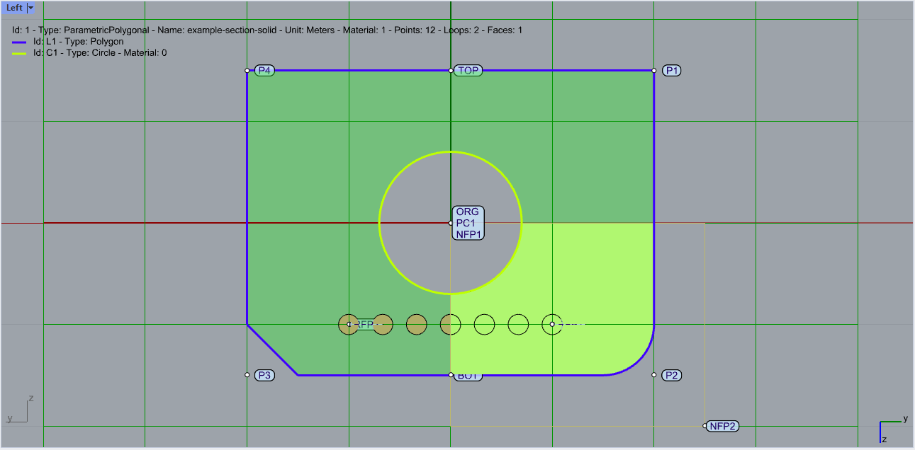
Figure 1. Overview solid section in Rhino#
Example Thin Walled Section#
And another example defining a thin walled section according predescribed json format.
![]()
example-section-thinWalled.json
{
    "Id": 2,
    "Name": "example-section-thinWalled",
    "Unit": "m",
    "MaterialId": 1,
    "ThinWalledSegments":
    [
      {
        "Id": "PTL",
        "Type": "PLAT",
        "PointStart": { "Id": "PTLStart", "Coord": [ 0.0, "+0.5*TH1" ] },
        "PointEnd":   { "Id": "PTLEnd",   "Coord": [ "-0.5*W", "+0.5*TH1" ] },
        "Thickness": "TH1"
      },
      {
        "Id": "PTR",
        "Type": "PLAT",
        "PointStart": { "Id": "PTRStart", "Coord": [ 0.0, "+0.5*TH1" ] },
        "PointEnd":   { "Id": "PTREnd",   "Coord": [ "+0.5*W", "+0.5*TH1" ] },
        "Thickness": "TH1"
      },
      {
        "Id": "PM",
        "Type": "PLAT",
        "PointStart": { "Id": "PMStart", "Coord": [ 0.0, "+TH1" ] },
        "PointEnd":   { "Id": "PMEnd",   "Coord": [ 0.0, "H" ] },
        "Thickness": "TH2"
      },
      {
        "Id": "WM",
        "Type": "WELD",
        "PointStart": { "Id": "WMStart", "Coord": [ 0.0, "+0.5*TH1" ] },
        "PointEnd":   { "Id": "WMEnd",   "Coord": [ 0.0, "+TH1" ] },
        "Thickness": "TH3"
      }
    ],
    "Variables": { "W": 4.0,  "H": 3.0, "TH1": 0.5, "TH2": 0.3, "TH3": 0.1, "rfDia": 0.1, "rfSpace": 0.3, "rfBDist": 0.5 },
    "VariableDescriptions":
    {
      "W":       "Width:Width of section",
      "H":       "Height:Height of section",
      "TH1":     "ThicknessTop:Thickness of top slab",
      "TH2":     "ThicknessMid:Thickness of vertical element",
      "TH3":     "ThicknessWeld:Thickness of weld",
      "rfDia":   "DiameterRf:Diameter of reinforcement",
      "rfSpace": "SpacingRf:Spacing of reinforcement",
      "rfBDist": "BorderDistRf:Border distance of reinforcement"
    },
    "LineReinforcements":
    [
      {
        "Id": "RF1",
        "Layer": "1",
        "MaterialId": "2",
        "Diameter": "rfDia",
        "BarDistribution": "FULL",
        "Spacing": "rfSpace",
        "PointStart": { "Id": "RFP1", "Coord": [ 0.0, "+TH1+rfBDist" ] },
        "PointEnd":   { "Id": "RFP2", "Coord": [ 0.0, "+H-rfBDist" ] }
      }
    ]
}
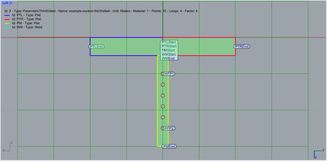
Figure 2. Overview thin walled section in Rhino#