SOFiMSHC Geometric Processing#
When exporting a geometry model from Rhino to SOFiSTiK, it will be passed to the geometry processing and meshing module SOFiMSHC. There are several geometric checks and processing tasks to be performed by the SOFiMSHC module before the model will be passed to the meshing kernel of SOFiSTiK.
There are two main tasks of geometric processing, namely geometric intersection and splitting of polysurfaces and periodic shapes. The processing steps in SOFiMSHC serve mainly the purpose to increase the FE mesh conformity and FE meshing stability, quality and success rate. Polysurfaces must be processed to be compatible with FE meshing conformity conditions.
The quality and stability of geometric processing in SOFiSTiK SOFiMSHC can be supported with FEA aware modelling. This help documentary will guide you through some issues of analysis aware modelling: Modeling Hints.
Geometry Intersection#
The SOFiSTiK SOFiMSHC module will try to produce a conforming finite element mesh (FE mesh) from the given geometric model generated in Rhino. Meaning, all coincide geometric elements like points, curves or surfaces will be merged and intersected with each other to ensure mechanical connectivity in FEA. The default behaviour of SOFiMSHC is to try to generate such a all-conforming FE mesh by geometrically processing the model from Rhino, unless explicitly specified differently by the user. In a local scope the user can suppress this conformity by selecting structural elements and changing ‘disable automatic intersection’ in the structural property dialog.
With automatic intersection enabled, elements whose distance is below a predefined tolerance will be merged. The tolerance can be defined within the Rhino SOFiSTiK menu:
All points, lines and surfaces of the original CAD model are intersected with each other in order to get geometrically unique elements at the boundaries. This cleaned-up model is then passed to the mesher which creates a surface FE mesh and beam elements.
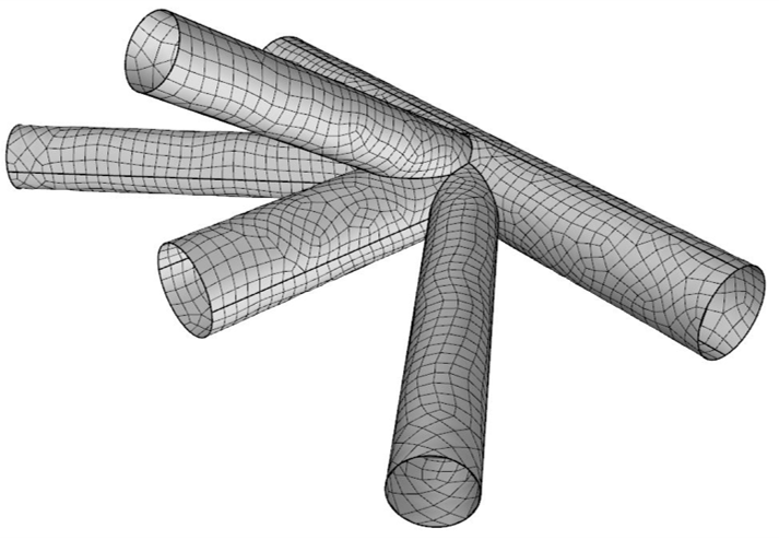
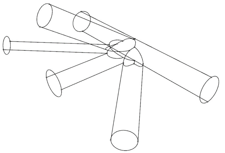
The following figures illustrate the geometry intersection workflow:
Original Rhino surfaces (topologically independent from each other)
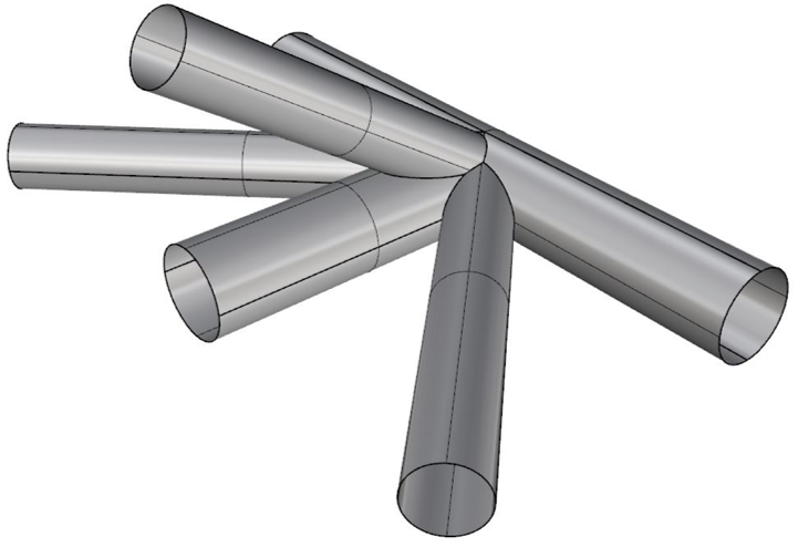
Original Intersected model with unique elements at the boundaries
Resulting finite element mesh with consistent nodes at surface borders