questions and answers#
When getting started with AutoCAD / SOFiCAD, there are usually some questions:
Drawing units#
The drawing units (meters, centimeters, millimeters) are controlled via the supplied SOFiCAD templates. The set drawing units in AutoCAD (_units) or Architecture (_AecDwgSetup) are adopted by SOFiCAD.
So if you select the template drawing Sofstart.dwt, it is provided with the units of meters. The template drawing Sofstart mm.dwt has the drawing units millimeters.
The use of the SOFiCAD template drawings is recommended, since for example already defined SOFiCAD dimensioning styles are included!
Where should construction work and where should labeling be carried out?#
The formwork can be created in the model area or in the model paper area, i.e. in the view window. If the formwork is larger, it makes more sense to create the complete formwork edges in the model area.
The scale-dependent elements such as texts, hatching and dimensions can be created in the model area and also in the model paper area (active viewport).
What is a model area#
In the model area you have an unlimited drawing area, without restricting the paper size!
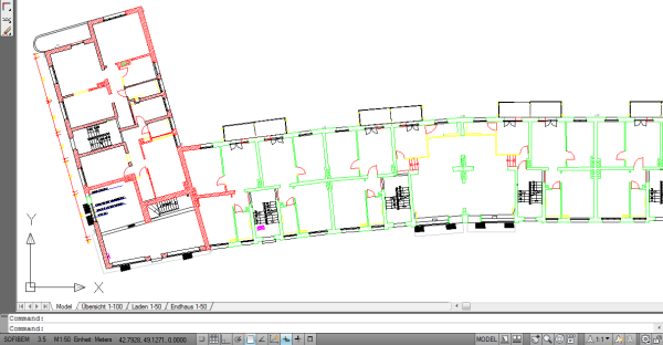
If you start with a SOFiCAD template drawing, the model area scale is 1:50. If required, this scale can be changed using the “Construction II” - “Plan” - “Construction” command.
What is a layout?#
The layout defines the paper area, whereby each layout can contain different plot settings and paper formats.
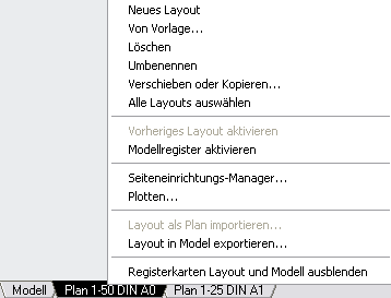
By right-clicking on the layout, the paper can be defined using the “Page Setup Manager”.
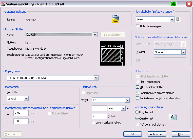
The page setup window looks like the plot window. Here you primarily determine the paper size. The plot scale must be 1: 1. The plotter and the plot style table used can be defined, so the settings in the plot window are omitted.
Result after page setup:
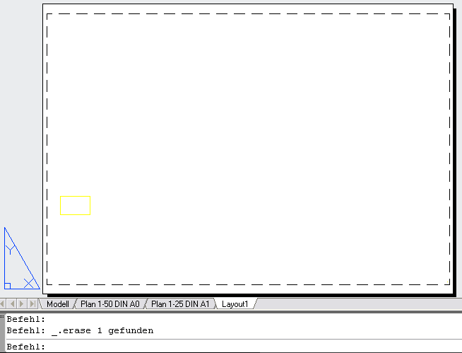
The paper format is shown, the dashed border is the printable area of the plotter.
What is in the paper area#
In the paper area there is the drawing margin with the folding markings, writing fields such as plan stamps and legends.
The paper area is identified by a right-angled blue triangle. If you are in the paper area, “PAPER” is activated in the status bar and the UCS symbol is shown in the paper area as a “triangle”.
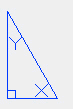
“PAPER” or “PAPER” appears in the status bar.

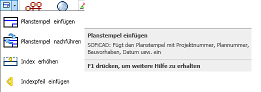
plan#
In the “Construction II” tab there is the “Plan” group
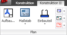
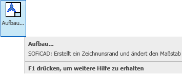
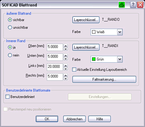
Using the “Structure…” command, the drawing margin with fold markings is created in the paper area.
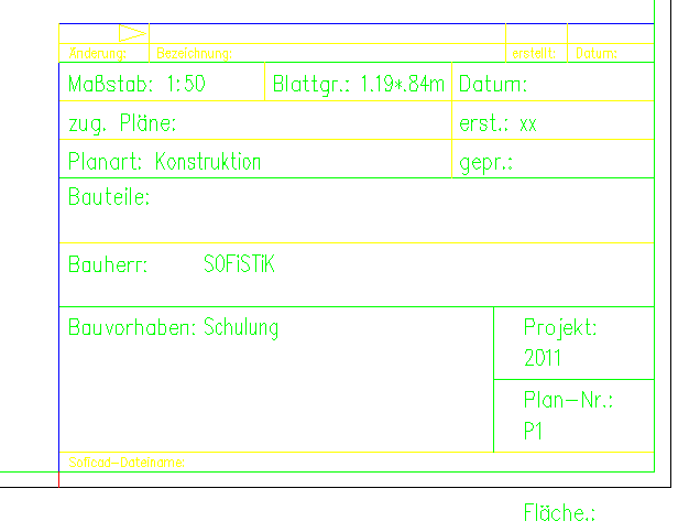
Insert the plan stamp in the paper area#
Block name of title block <PLKO->:
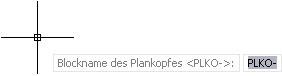
The block name for the title block must start with PLKO-… . The following designation can be used to identify different plan stamps. The standard stamp from SOFiCAD is used with PLKO-.DWG.
Then the plan type is asked:
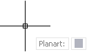
Todo planar selection
Enter attributes for the plan stamp:
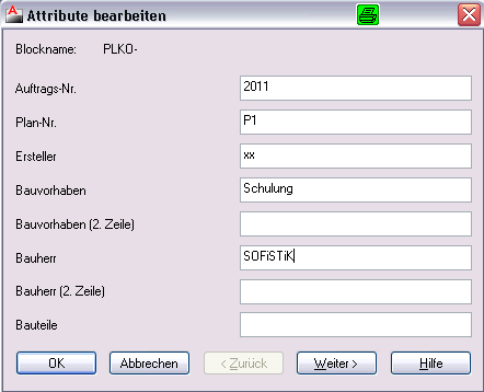
The plan stamp is inserted in the lower right corner of the layout.
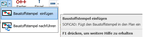
Insert building material stamp in the paper area
The block name for the building material stamp must begin with BSTOFF-… . Different building material stamps can be identified with the following designation. With BSTOFF -.DWG the standard stamp from SOFiCAD is used.
Enter attributes for the building material stamp:
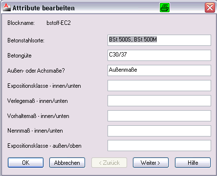
The building material stamp is inserted into the layout.
Viewport#
A viewport is a section of the formwork in the model area. You could also imagine that the paper area would be a daily newspaper and you would look at a detail through a cutout / hole. This section of your “drawing elements” must be scaled, otherwise you would not recognize the elements. Thus, the viewport must scale the elements using a “zoom scale”.
With an existing viewport, you change the scale by selecting the viewport in the paper area and right-clicking. In the right-click menu “Set view window” appears.
New viewports are created using “Construction II - Plan - Scale”.
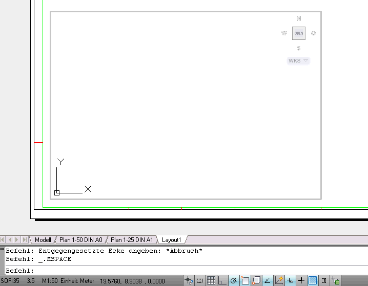
If a view window is activated by double-clicking in this window, you are in the paper model area. This means that everything that is drawn is also available in the model area.
The viewport is optically marked and the coordinate symbol is visible. “MODEL” can be read in the status bar.
The individual viewports can be switched to the corresponding viewport with a double click.
World and user coordinates#
There are two coordinate systems: a fixed coordinate system, called the world coordinate system (WCS), and a movable coordinate system, which is also called the user coordinate system (UCS). By default, these two systems match in a new drawing.
You can move and rotate the user coordinate system to simplify entering coordinate values, displaying grids, ortho mode, setting viewports, and other drawing tools.
The symbol for world coordinates is shown as follows:

The user coordinate icon is represented as follows:
