Post Tensioned Concrete Beam Bridge#
Introduction#
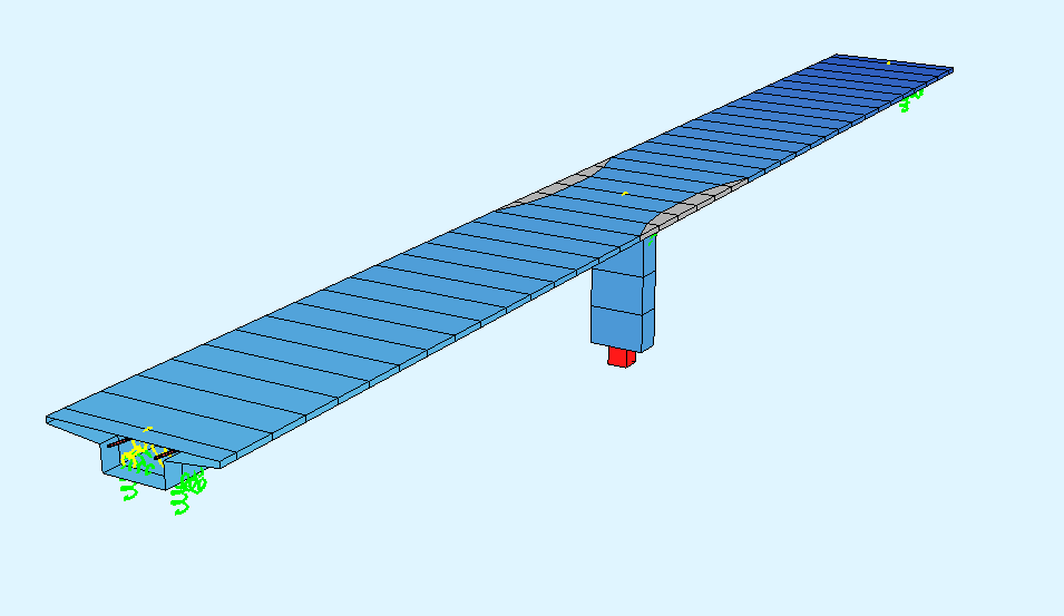
This tutorial deals with a simple 2-span post tensioned concrete beam bridge. The analytical model of the bridge consists only of beam elements (superstructure and columns).
Note
A basic SOFiSTiK knowledge is required for this tutorial. The standard workflow is explained inside the General Workflow description. Inside this tutorial we show only the project specific workflows, which are different from the basic workflow.
Objectives#
Project Description#
The idea of this tutorial is to guide you through a simple PSC (Pre-stressed Concrete) bridge project and introduce the general work-flow showing the necessary program tools and functions. All steps like modeling, loading, traffic loads, combinations etc. are simplified.
Bridge Axis#
The following table shows the main spans and stations for the axis definition.
Spans [m] |
- |
0.70 |
- |
26.60 |
- |
26.60 |
- |
0.70 |
- |
Stations [m] |
10.0 |
- |
10.70 |
- |
37.30 |
- |
63.90 |
- |
64.60 |
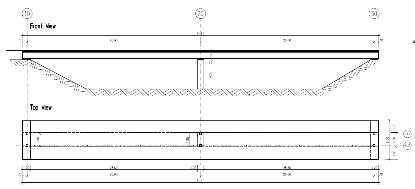
Along the bridge axis we will use a variable for the non-effective parts of the cross sections. Please see the following table with the necessary input values.
Station [m] |
0.00 |
33.30 |
34.80 |
39.80 |
41.10 |
64.60 |
#NEFF [m] |
3.00 |
3.00 |
2.30 |
2.30 |
3.00 |
3.00 |
Bridge Materials#
The following table show the necessary materials. As you can see, we are using different material numbers for bridge deck and column, although the concrete material is the same. This is a common setting inside SOFiSTIK to be able to split up the results for a better overview.
Number |
Title |
Strength |
|---|---|---|
1 |
Concrete bridge deck |
C 40/50 |
11 |
Concrete pier |
C 40/50 |
2 |
Reinforcement steel |
B 500 |
3 |
Reinforcement steel stirups |
B 500 |
4 |
Prestressing steel |
Y 1770 |
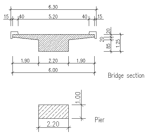
Cross sections#
Number |
Title |
Dimensions |
|---|---|---|
1 |
Pier |
b/h = 2.20m / 1.00m |
Construction stages#
Stage Number |
Title |
|---|---|
10 |
Self weight pier (AUTO GRP 10) |
15 |
C+S pier only |
20 |
Self weight of bridge deck |
21 |
Prestressing of bridge deck |
25 |
C+S |
30 |
ADL (Additional dead load) (Loadcase 2) |
35 |
C+S traffic opening |
45 |
C+S infinite |
Design code#
This tutorial is based on Eurocode EN 1992.
Starting a new project#
First we create a new SSD project and save it inside a project directory on your local computer. For further information see chapter Start New SSD Project in the General Workflow description.
Defining materials#
Generate all necessary materials listed above. Follow the procedures explained in chapter Material Definition in the General Workflow description.
Defining Cross Sections#
In this project we have only one standard cross section for the pier. Please generate a new rectangular cross section with the dimensions and material properties listed above. Follow the procedures explained in chapter Cross Section Definition in the General Workflow description.
The main bridge section will be defined graphically inside SOFiPLUS with the cross section editor.
Note
For the main bridge section we want to use a variable for the non effective parts of the cross sections. This variable will be defined within the bridge axis definition in SOFiPLUS. Therefore we recommend to create the bridge axis with all settings first.
Prestressing systems#
Please generate a new prestressing system number 1, with a VSL 6-12 multistrand system, see picture below.
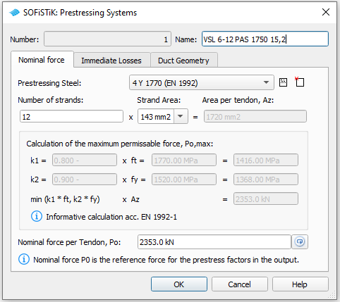
Follow the procedure explained in chapter Prestressing System in the General Workflow description.
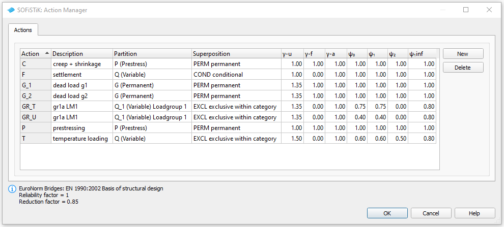
Actions#
Before we define any load, we must define all necessary actions within the SSD “Action Manager”. In our bridge example we need the following actions.
System Generation in SOFiPLUS#
The bridge geometry will be defined using the CABD concept inside SOFiPLUS. For that we will work through the following steps:
Define main bridge axis
Define placements along the bridge axis
Define variables (will be used for the main cross section)
Generate master cross section within Cross Section Editor
Generate structure lines representing the main bridge construction
Use the Cross Members Editor to generate the support construction containing springs and couplings
Make a final check of the system and align elements if necessary
The following videos will show the main steps to generate the system.
Generate Bridge Axis#
The following video will show the axis generation workflow.
Generate Master Cross Section#
The following video will show the cross section generation workflow within the cross section editor.
System Generation#
The following video will show the system generation workflow.
Tendon Generation#
The following video will show the tendon generation workflow.
Loads#
The loads will be defined inside SOFiPLUS(-X). First define the necessary loadcases inside the Loadcase Manager. Then create the loads and allocate the loads to the loadcases.
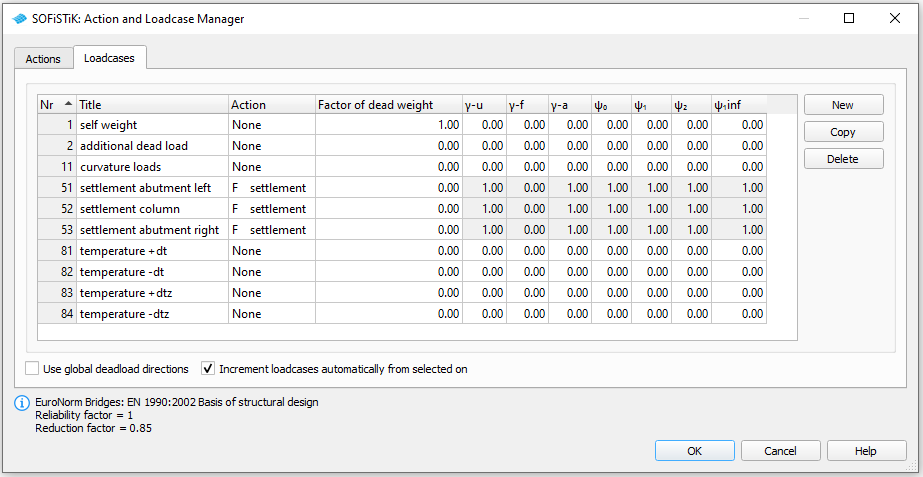
After defining the load cases we generate the loads in SOFiPLUS. First we select an element related line load. Defining the load we select the structural lines and define a line load of 9 kN/m. In every support axis we define a settlement wzz = 10 mm and save the loads within the load cases 51 to 53. For the temperature loads we generate 4 loadcases 81 to 84 containing the basic temperature loads
LC |
Action |
Designation |
|---|---|---|
81 |
NONE |
constant temperature DT = + 20°C |
82 |
NONE |
constant temperature DT = - 20°C |
83 |
NONE |
temperature difference DTZ = -12.3°C |
84 |
NONE |
temperature difference DTZ = +8.0°C |
Warning
Load cases which will be used later on inside the CSM should be saved within the action container NONE. With this concept the load cases will not be used twice in case the user defines his own combination rules using actions only!
For further processing including the necessary temperature combinations please see the chapter Define Actions and Loads in the General Workflow description.
Linear Analysis#
The linear analysis will be processed only for the settlement and temperature loads. Therefore the selection will be done manually. Please see the chapter Linear Analysis in the General Workflow description.
Generate Envelope from Traffic Loads#
As already explained in the general workflow it is necessary to run at least one linear load case before evaluating the traffic loads with the influence line method. We recommend to do this analysis before the construction stage analysis to use the full developed stiffness matrix from the complete bridge.
Note
The stiffness effects of the elements were already used within the linear analysis. The following influence line evaluation will therefore be processed on that basis. Additional settings are not necessary.
For a general description of the input workflow please take a look at the task description in our online help.
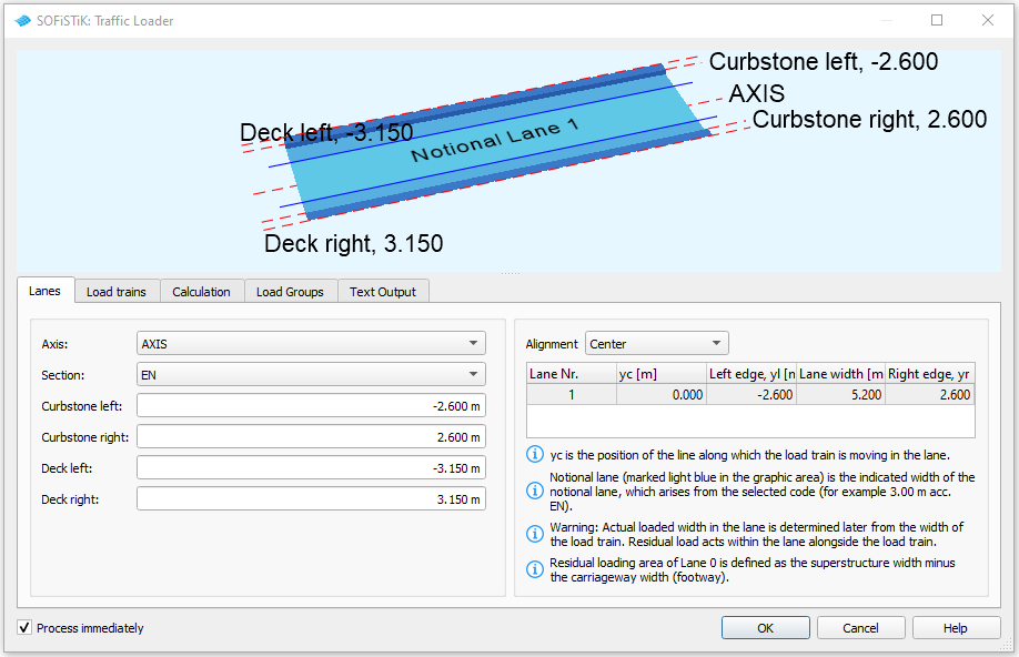
For our little example we have a small bridge with a total width of 6.3 m. First select an existing bridge axis and define the width of the traffic lane and bridge. The program will then automatically generate lanes.
Next you define the load trains and the desired results. In our case we are interested only in the beam results for further design of the composite cross sections.
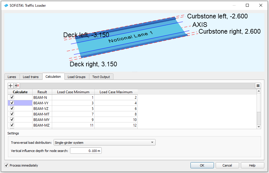
For the results it is necessary to define different load groups and evaluation cases. Usually it is convenient to separate the results for tandem axes and udl loads. The evaluation results will be saved again in a predefined action container.
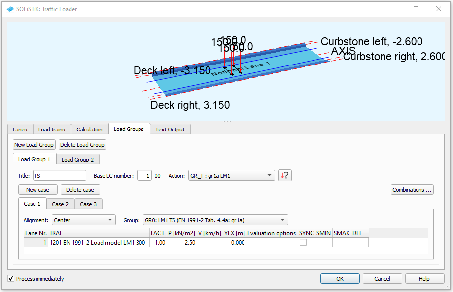
The loads on the footway will be defined as an extra evaluation case inside the UDL load group. In that case we need special combinations from UDL and Footway loads. Simply use the combination button inside the dialogue and generate the combinations. After the input is correct and finished you may close the dialogue and process immediately the analysis. Again we recommend to add a task “Interactive Graphic” to display the important results.
Define Construction Stages#
For post tensioned concrete bridges we need the construction stages for the evaluation of different cross section properties based on the open and filled ducts for the tendons as well as for creep and shrinkage analysis. Insert the SSD tasks “Construction Stages” and fill in the stages as defined in table Construction Stages above.
For our example the following input must be done inside the task “Construction Stage Manager”.
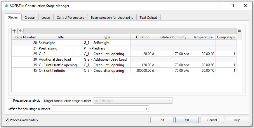
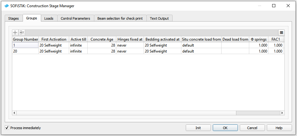
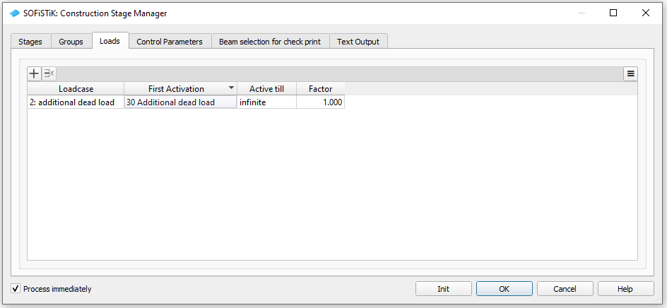
For further explanations please see also the chapter Construction Stages in the General Workflow description and the task description in our online help.
Combinations#
Please follow the explanations of chapter Combinations and Superpositioning from the General Workflow description.
Design#
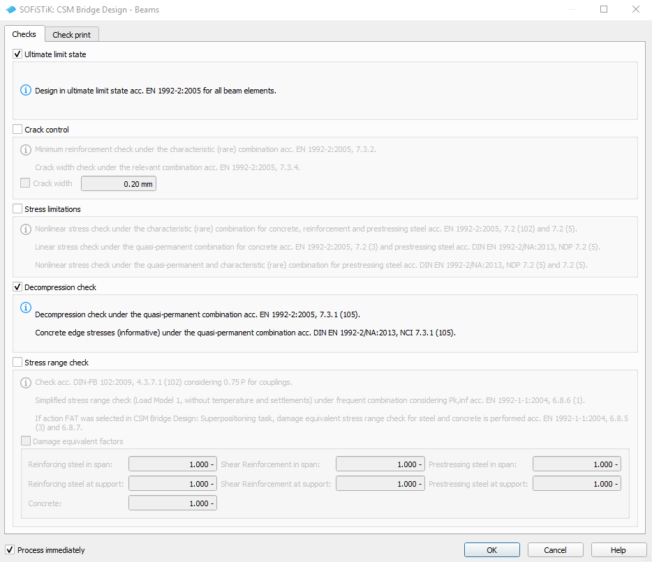
According to the code selected at the beginning of the project, several design checks are necessary. Again, the module CSM is able to generate all necessary design checks automatically. Simply add a new Task “CSM Bridge Design - Beams” to your project. You may select the necessary design checks inside this task. In case you want to separate the different design checks, you may insert this task multiple times with different settings.
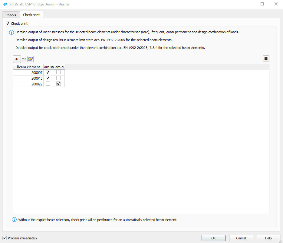
For a detailed output of specific beam sections, you may select these sections graphically from the ANIMATOR. The selection is saved inside the task on tab “Beam selection for check print”.
Note
This task is only available after the task “CSM Bridge Design - Superpositioning” was added to your project!
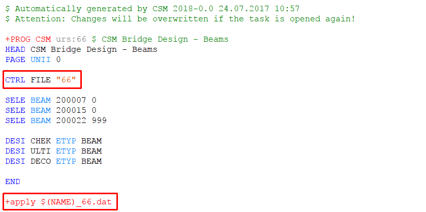
With every CSM run a new file $(name)_xxx.dat is generated automatically. The variable $(name) represents the project name and the XXX represents a number. If you right click on the task “CSM Bridge Design - Beams” > “Test Editor” you may open the text file generated by this task. There you will see the number generated by the program, which will be used for the new generated file.
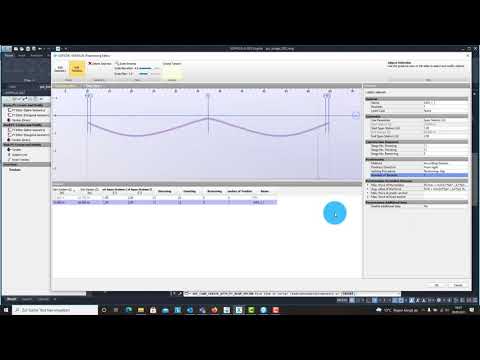
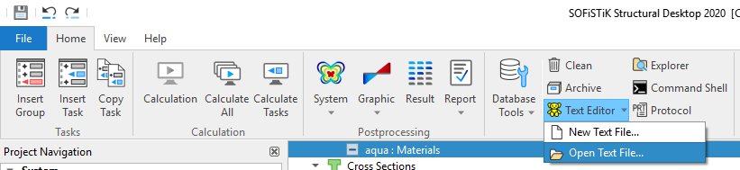
It is always helpful to have a view inside this generated TEDDY input file. You may open this file from the menu bar, TEDDY icon > “Open Text File”. See the following picture.
Documentation#
For the final documentation, you can collect all single reports and generate a complete document. Please follow the explanations of chapter Generate Report from the General Workflow description.