Concrete Slab Bridge#
Introduction#
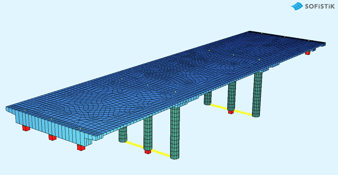
This tutorial deals with a simple 3-span concrete slab bridge. The analytical model of the bridge consists of shell elements and beam elements for the columns.
Note
A basic SOFiSTiK knowledge is required for this tutorial. The standard workflow is explained inside the General Workflow description. Inside this tutorial we show only the project specific workflows, which are different from the basic workflow.
Objectives#
Starting a new project
Define Materials
Define Cross Sections
Generate System and Loads inside SOFiPLUS
Linear analysis
Live load analysis
Construction Stages
Design
Project Description#
The idea of this tutorial is to guide you through a simple RC (Reinforced-Concrete) bridge project and introduce the general work-flow showing the necessary program tools and functions. All steps like modelling, loading, traffic loads, combinations etc. are simplified.
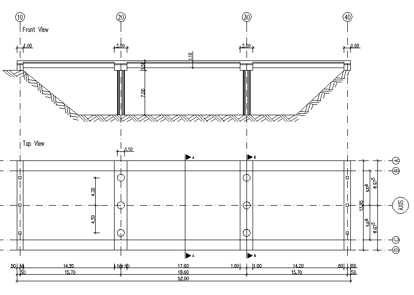
Bridge Axis:#
The bridge has 3 spans with small cantilevers at the beginning and at the end of the bridge.
Spans [m] |
0.50 |
15.70 |
19.60 |
15.70 |
0.50 |
- |
||||||
Stations [m] |
10.00 |
10.50 |
11.50 |
25.20 |
26.20 |
27.20 |
44.80 |
45.80 |
46.80 |
61.00 |
61.50 |
62.00 |
Bridge Materials:#
For the bridge we will use the following materials.
Number |
Title |
Strength |
|---|---|---|
1 |
Concrete bridge deck |
C 40/50 |
2 |
Reinforcement steel deck |
B 500 |
11 |
Concrete Pier |
C 40/50 |
12 |
Reinforcement Steel Pier |
B 500 |
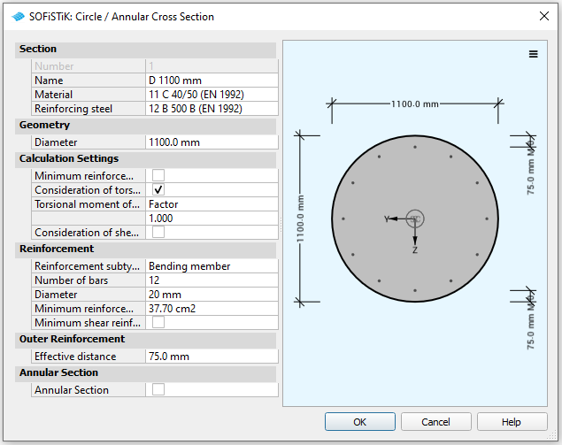
Cross sections#
Number |
Title |
Dimensions |
|---|---|---|
1 |
Column |
D = 1.100 m |
Code#
This tutorial is based on the Eurocode EN 1992-2004
Starting a new project#
First we create a new SSD project and save it inside a project directory on your local computer. For further information see chapter Start New SSD Project in the General Workflow description.
Defining materials#
Generate all necessary materials listed above. Follow the procedures explained in chapter Material Definition in the General Workflow description.
Defining Cross Sections#
In this project we have only one standard cross section for the pier. Please generate a new rectangular cross section with the dimensions and material properties listed above. Follow the procedures explained in chapter in Cross Section Definition in the General Workflow description.
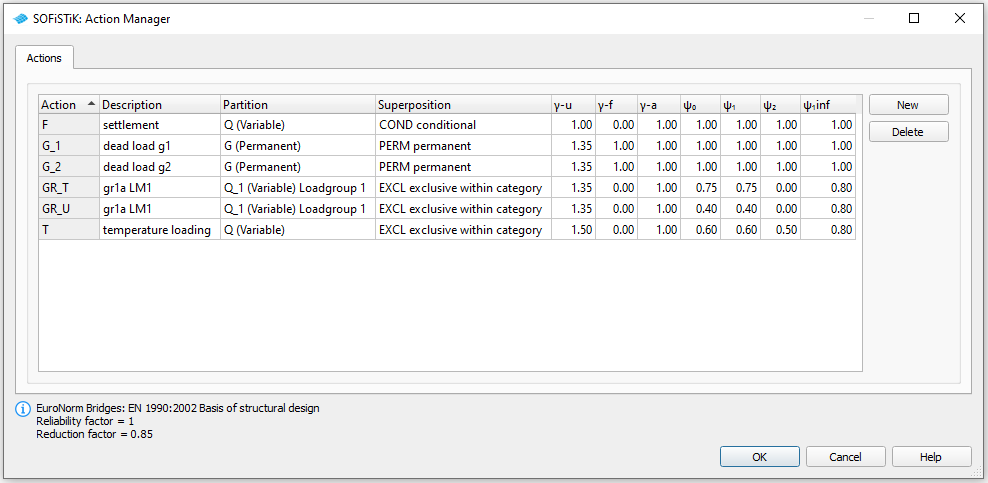
Actions#
With the Action Manager we define all necessary actions before we start the system generation inside SOFiPLUS.
System Generation in SOFiPLUS#
The bridge geometry will be defined using the CABD concept inside SOFiPLUS. For that we will work through the following steps:
Define main bridge axis
Define placements along the bridge axis
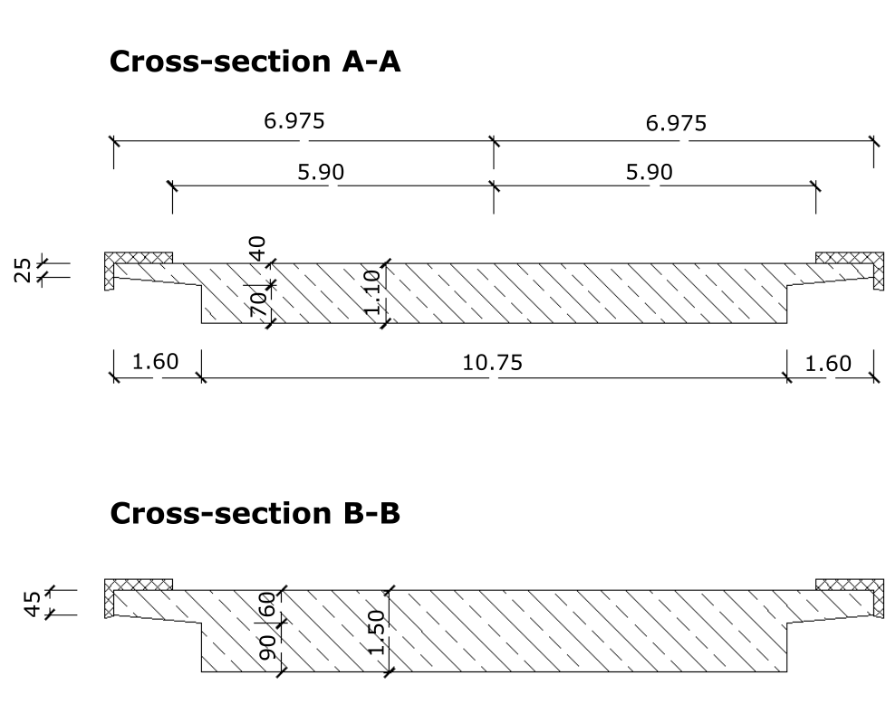
Generate structure areas with varying thickness representing the main bridge deck.
Use the Cross Members Editor to generate the support construction and piers containing springs and couplings.
Make a final check of the system and align elements if necessary
Generate Bridge Axis#
Generate the main bridge axis including secondary axis with the geometry information from the project description. For further information see chapter Start New SSD Project in the General Workflow description.
System Generation#
The following video will show the system generation workflow.
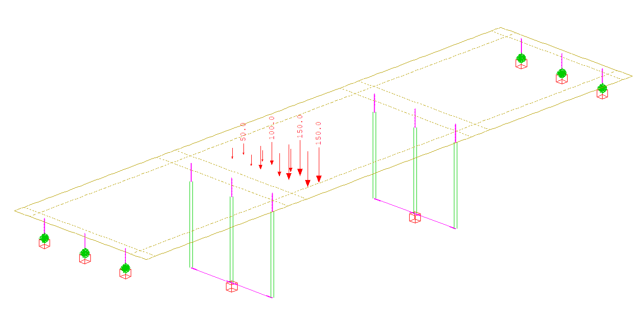
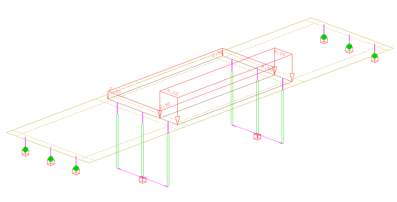
Loads#
In our bridge example we need the following load cases and define all of them inside SOFiPLUS with the Loadcase Manager. Note that the self-weight and additional dead loads will be processed later by the “Construction Stage Manager”. Therefore we save them within the action container NONE. With this concept we make sure that the load cases will not be used twice in combinations!
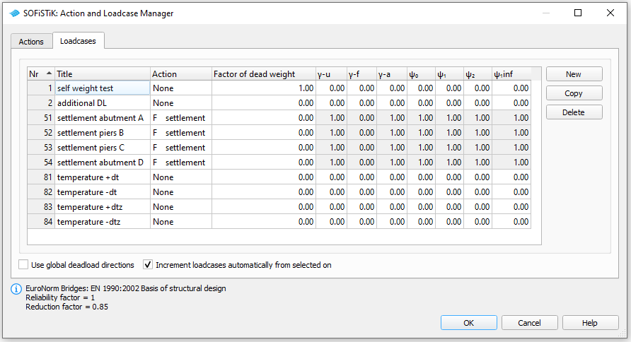
For additional dead loads we will apply a uniform distributed load of 2.5 kN/m² on all areas. In every support axis we define a settlement wzz = 10 mm and save the loads within the load cases 51 to 53. For the temperature loads we generate 4 loadcases 81 to 84 containing the basic temperature loads
LC |
Action |
Designation |
|---|---|---|
81 |
NONE |
constant temperature DT = + 20°C |
82 |
NONE |
constant temperature DT = - 20°C |
83 |
NONE |
temperature difference DTZ = -12.3°C |
84 |
NONE |
temperature difference DTZ = +8.0°C |
For further processing including the necessary temperature combinations please see the chapter Define Actions and Loads in the General Workflow description.
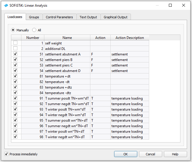
Linear Analysis#
After all standard loads like self weight, temperature and settlement are defined we insert a new task “Linear Analysis”. Inside this task we change the load case selection from automatic to manual. With this we make sure that only the selected loads are computed in this task, if we later create further loadcases.
Traffic Loads#
Next we proceed with the traffic loads. Besides the general method with the influence line method we want to introduce a second method to apply the traffic loads on the bridge. This method is called the “Load Stepping Method”. This method is a very straight forward method with lot’s of single load cases, which will be analysed and superposed to get the envelopes for the further design tasks.
Load Case Numbering#
Processing this method for the evaluation of traffic loads we need first a list of all necessary loadcases. We recommend the following numbering system:
LC |
Action |
Designation |
|---|---|---|
1201 |
NONE |
load train with load model LM1and 300 kN axle load |
1202 |
NONE |
load train with load model LM1and 200 kN axle load |
1203 |
NONE |
load train with load model LM1and 100 kN axle load |
201 - 225 |
NONE |
GR_T load stepping TS right most |
301 - 325 |
NONE |
GR_T load stepping TS left most |
401 - 425 |
NONE |
GR_T_T load stepping TS center |
501 - 503 |
NONE |
GR_U load stepping UDL right most; 3 spans |
521 - 523 |
NONE |
GR_U load stepping UDL left most; 3 spans |
541 - 543 |
NONE |
GR_U load stepping UDL center; 3 spans |
561 - 563 |
NONE |
GR_U footway and cycle track; 3 spans |
601 - 628 |
GR_T |
GR_T envelope GR_T |
701 - 728 |
NONE |
GR_U envelope GR_U right most + footways; 3 spans |
731 - 758 |
NONE |
GR_U envelope GR_U left most + footways; 3 spans |
760 - 788 |
NONE |
GR_U envelope GR_U center + footways; 3 spans |
631 - 658 |
GR_U |
GR_U envelope GR_U; 3 spans |
Workflow Load Stepping Method#
The following steps are necessary to perform this analysis (create “User Tasks” for each step and insert the code blocks):
Define lanes within SOFiLOAD module. The correct input looks like:
+prog sofiload
head 'Lanes'
echo lane full
sto#start 10.00 $ station value bridge begin
$ For load stepping method together with SOFiLOAD COPY
$ it is necessary to define the bridge spans
$ this will be done with SA and SE input.
lane 'AXIS' type ec wr 5.90 wl -5.90 yra 6.9750  yla -6.9750 $$
      sa #start+0.00        se #start+16.20
      sa #start+16.20       se #start+16.20+19.60
      sa #start+16.20+19.60 se #start+16.20+19.60+16.20
end
With this input a number of traffic lanes are created (depending on the specified width between the curbstones). The standard setting is that the lanes 10, 11, 12,… represent a positioning of the lanes adjusted to the right and those with numbers 20, 21, 22 a positioning to the left. Usually the lanes with numbers 1, 2, 3,… are related to a centric positioning.
Note
An exception are cases where the width between the curbstones can be “exactly” covered by the traffic lanes (e.g. where the remaining space between the curbstones that is not covered by lanes is smaller than 0.3 m). In this case the lanes 1, 2, 3,.. are created with equal width and positioned in ascending order from right to left.
Define load trains within SOFiLOAD module. The loads are saved in the following load cases:
+prog sofiload
head 'Load Models'
echo load yes
lc 1201 type none ; trai LM1 300  $ LM1 double axle load 300 kN
lc 1202 type none ; trai LM1 200  $ LM1 double axle load 200 kN
lc 1203 type none ; trai LM1 100  $ LM1 double axle load 100 kN
end
Generate a series of load cases for TS loads including different positions within the lanes (center, most right, most left):
+prog sofiload
head 'Load Stepping LM1 TS'
echo full no
echo load yes

sto#l_bridge 16.20+19.60+16.20
sto#n_steps  25                $ steps for discrete load-postions
sto#trai 1201,1202,1203        $ load trains, defined in advanced

$ loadcase numbers
sto#lc_min1  201               $ starting loadcase for location in carriageway case 1
sto#lc_min2  301               $ starting loadcase for location in carriageway case 2
sto#lc_min3  401               $ starting loadcase for location in carriageway case 3

sto#lc_max1  0                 $ last loadcase
sto#lc_max2  0                 $ last loadcase
sto#lc_max3  0                 $ last loadcase

$ case 1 (right most +y local)
$ laneset 10

  loop#j #n_steps                                                   $ loop for loadcases
    let#pos  1+#j
        lc #lc_min1 type none  titl 'LM1:TS Lane 10/11/12 pos#pos'
        copy no #trai(0) fact 1.0 type gr0 ref 'axis.10' dx #j*#l_bridge/(#n_steps-1)+#start
        copy no #trai(1) fact 1.0 type gr0 ref 'axis.11' dx #j*#l_bridge/(#n_steps-1)+#start
        copy no #trai(2) fact 1.0 type gr0 ref 'axis.12' dx #j*#l_bridge/(#n_steps-1)+#start
        let#lc_min1  #lc_min1+1
   endloop
 sto#lc_max1 #lc_min1-1

$ case 2 (left most -y local)
$ laneset 20

  loop#j #n_steps                                                   $ loop for loadcases
    let#pos  1+#j
        lc #lc_min2 type none  titl 'LM1:TS Lane 20/21/22 pos#pos'
        copy no #trai(0) fact 1.0 type gr0 ref 'axis.20' dx #j*#l_bridge/(#n_steps-1)+#start
        copy no #trai(1) fact 1.0 type gr0 ref 'axis.21' dx #j*#l_bridge/(#n_steps-1)+#start
        copy no #trai(2) fact 1.0 type gr0 ref 'axis.22' dx #j*#l_bridge/(#n_steps-1)+#start
        let#lc_min2  #lc_min2+1
   endloop
 sto#lc_max2 #lc_min2-1

$ case 3 (centric)
$ laneset 1

  loop#j #n_steps                                                   $ loop for loadcases
    let#pos  1+#j
        lc #lc_min3 type none  titl 'LM1:TS Lane 1/2/3 pos#pos'
        copy no #trai(0) fact 1.0 type gr0 ref 'axis.1' dx #j*#l_bridge/(#n_steps-1)+#start
        copy no #trai(1) fact 1.0 type gr0 ref 'axis.2' dx #j*#l_bridge/(#n_steps-1)+#start
        copy no #trai(2) fact 1.0 type gr0 ref 'axis.3' dx #j*#l_bridge/(#n_steps-1)+#start
        let#lc_min3  #lc_min3+1
   endloop
 sto#lc_max3 #lc_min3-1

end
Generate a series of load cases for UDL loads including different positions within the lanes (center, most right, most left)
+prog sofiload
head 'Load Stepping LM1 UDL'
echo full extr
echo load yes

sto#n_spans  3                    $ number of spans

$ loadcase numbers
sto#lc_minu1  501                 $ starting loadcase
sto#lc_minu2  521                 $ starting loadcase
sto#lc_minu3  541                 $ starting loadcase
sto#lc_minur  561                 $ starting loadcase

sto#lc_maxu1  0                   $ last loadcase
sto#lc_maxu2  0                   $ last loadcase
sto#lc_maxu3  0                   $ last loadcase
sto#lc_maxur  0                   $ last loadcase

$ case 1 (right most +y local)
$ laneset 10

  loop#j #n_spans                                                   $ loop for loadcases
    let#span  1+#j
        lc #lc_minu1 type none  titl 'LM1:UDL Lane 10/11/12/r span#span'
        copy no #trai(0) fact 1.0 type gru ref 'axis.10' dx 0 from #span to - inc 0
        copy no #trai(1) fact 1.0 type gru ref 'axis.11' dx 0 from #span to - inc 0
        copy no #trai(2) fact 1.0 type gru ref 'axis.12' dx 0 from #span to - inc 0
        let#lc_minu1  #lc_minu1+1
   endloop
 sto#lc_maxu1 #lc_minu1-1

$ case 2 (left most -y local)
$ laneset 20

  loop#j #n_spans                                                   $ loop for loadcases
    let#span  1+#j
        lc #lc_minu2 type none  titl 'LM1:UDL Lane 20/21/22/r span#span'
        copy no #trai(0) fact 1.0 type gru ref 'axis.20' dx 0 from #span to - inc 0
        copy no #trai(1) fact 1.0 type gru ref 'axis.21' dx 0 from #span to - inc 0
        copy no #trai(2) fact 1.0 type gru ref 'axis.22' dx 0 from #span to - inc 0
        let#lc_minu2  #lc_minu2+1
   endloop
 sto#lc_maxu2 #lc_minu2-1

$ case 3 (centric)
$ laneset 0

  loop#j #n_spans                                                   $ loop for loadcases
    let#span  1+#j
        lc #lc_minu3 type none  titl 'LM1:UDL Lane 1/2/3/r span#span'
        copy no #trai(0) fact 1.0 type gru ref 'axis.1' dx 0 from #span to - inc 0
        copy no #trai(1) fact 1.0 type gru ref 'axis.2' dx 0 from #span to - inc 0
        copy no #trai(2) fact 1.0 type gru ref 'axis.3' dx 0 from #span to - inc 0
        let#lc_minu3  #lc_minu3+1
   endloop
 sto#lc_maxu3 #lc_minu3-1

$ footways and cycle tracks ! = type gr3
$ laneset 0
  loop#j #n_spans                                                  $ loop for loadcases
    let#span  1+#j
        lc #lc_minur type none  titl 'LM1: Footways span#span'
        copy no #trai(0) fact 1.0 type gr3 ref 'axis.0' dx 0 from #span to - inc 0
        let#lc_minur  #lc_minur+1
   endloop
 sto#lc_maxur #lc_minur-1

end
Perform a linear analysis of all single load cases. Instead of using the task “Linear Analysis” we will use a task “Text Editor (TEDDY)” including the load case number variables we defined before. This enables us to use this task without changes in additional project files.:
+PROG ASE $ Linear Analysis
HEAD 'Analysis of Traffic Loads
PAGE UNII 0
CTRL OPT SOLV VAL - $  Solution of the system
LC (#lc_min1 #lc_max1 1)
LC (#lc_min2 #lc_max2 1)
LC (#lc_min3 #lc_max3 1)

LC (#lc_minu1 #lc_maxu1 1)
LC (#lc_minu2 #lc_maxu2 1)
LC (#lc_minu3 #lc_maxu3 1)
LC (#lc_minur #lc_maxur 1)
END
Create combinations and superposition for the TS envelope. All Loadcases from 201 to 225, from 301 to 325 and from 401 to 425 are acting exclusively. The results will be saved inside the action GR_T for further access. The commands using a standard combination look like that (take a look a the CADINP input of the example file for further details):
comb 1 stan base 0 type GR_T
lc (201  225 1) type a1   $ a1 -> mutually exclusive
...
Create combinations and superposition for the UDL envelope. Before we generate the envelope from all the UDL loads we must create additional combinations for the three evaluation cases (most right, most left, center) + footway loads. From these results we evaluate the final envelope for UDL loads. Take a look at the CADINP input of the example file for further details.
As an option you may delete all load cases you do not user later on in the analysis. This can be done within a task “Text Editor (TEDDY)” and the following input example:
+PROG ASE
HEAD 'Delete unused LCs'
ECHO FULL NO
 LC (#lc_min1  #lc_max1 1)   type del
 LC (#lc_min2  #lc_max2 1)   type del
 LC (#lc_min3  #lc_max3 1)   type del
 LC (#lc_minu1  #lc_maxu1 1) type del
 LC (#lc_minu2  #lc_maxu2 1) type del
 LC (#lc_minu3  #lc_maxu3 1) type del
 LC (#lc_minur  #lc_maxur 1) type del
 LC (#lcu1  #lcu1+16 1)      type del
 LC (#lcu2  #lcu2+16 1)      type del
 LC (#lcu3  #lcu3+16 1)      type del
END
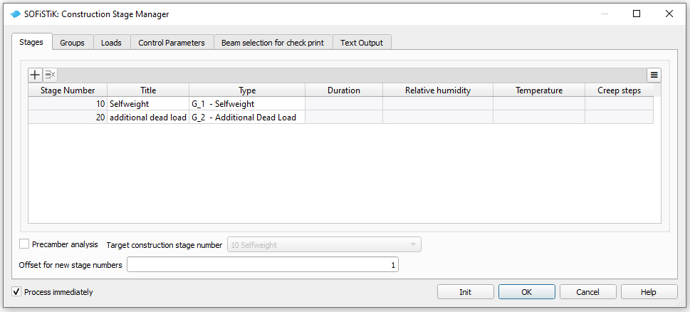
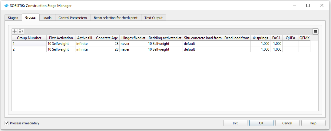
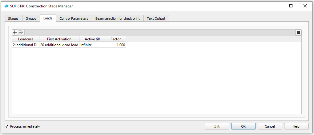
Construction Stages#
For this simple example it would also be possible to do without the definition of construction stages. However the application of the “Construction Stage Manager” is a prerequisit to use the CSM Design tasks (see sequel). For this reason we will define construction stages where the self-weight and additional dead loads are activated. Insert the SSD task “Construction Stages” and modify its settings as shown in the pictures below.
For further explanations please see also the chapter Construction Stages in the General Workflow description and the manual of module CSM.
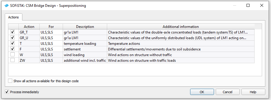
Combinations#
Insert the task “CSM Bridge Design - Superpositioning” in your project and run it.
Design Area Elements#
For the design of area elements several steps must be followed
define design parameters for area elements
perform ULS and SLS design checks
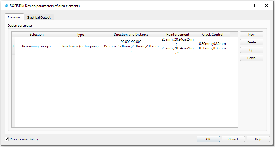
Design Parameters#
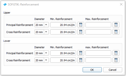
First of all you must define the design parameters of the area elements. These are reinforcement directions, distances, diameters and allowable crack width. To do that simply use the task “Design Parameter Area Elements”.
Note
The main reinforcement, which by definition is the outer reinforcement, is always facing in the same direction as the local x-axes of the QUAD elements. For a standard slab bridge the outer reinforcement direction is usually provided transversely to the sides of the bridge, which is usually the local y-axes. Therefore please set an angle of 90° for the upper and lower principal reinforcement. (see the following picture)
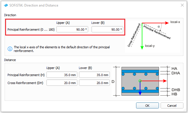
Diameter and reinforcement area will be defined in the tab “Reinforcement”
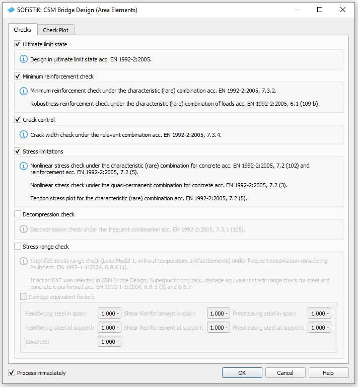
ULS Design#
To design the area elements simply add the task “CSM Bridge Design (Area Elements)” in the task tree. In the task you can select the design checks that you want to perform.
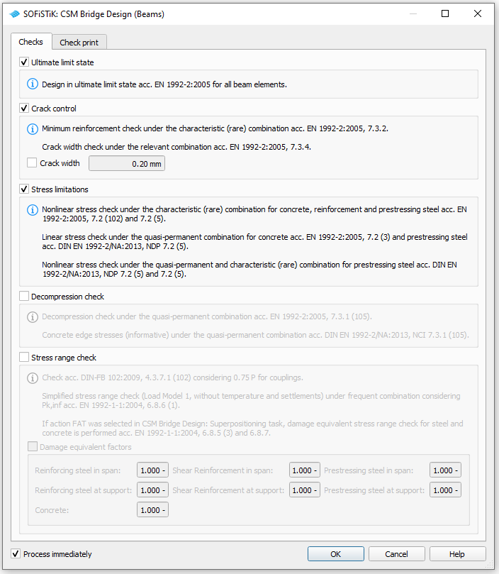
Design Beam Elements#
For the design checks of the beam elements we use the task “CSM Bridge Design (Beams)”. Add the task in the SSD and select the checks you want to perform.
Documentation#
For the final documentation, you can collect all single reports and generate a complete document. Please follow the explanations of chapter Generate Report from the General Workflow description.