General Workflow Bridge Design#
Project Work - Step by Step#
The general workflow sequence inside SOFiSTiK using SSD and SOFiPLUS is recommended as follows:
For practical examples and further information about the detailed input please see the available bridge tutorials.
Start a New SSD Project#
Important
This is a general description, which can be different from the project discussed in this tutorial. Please make the necessary adjustments by yourself.
Title: Create a New SSD Project | Quality: 1080p HD | Captions: English
We recommend to use a local directory for your project files to speed up communication between program and database. Later on you can zip and save your project data on a company server.
If you leave the System Information dialogue with the selected code is fixed and saved inside the database. You may NOT change the code later on within this dialogue.
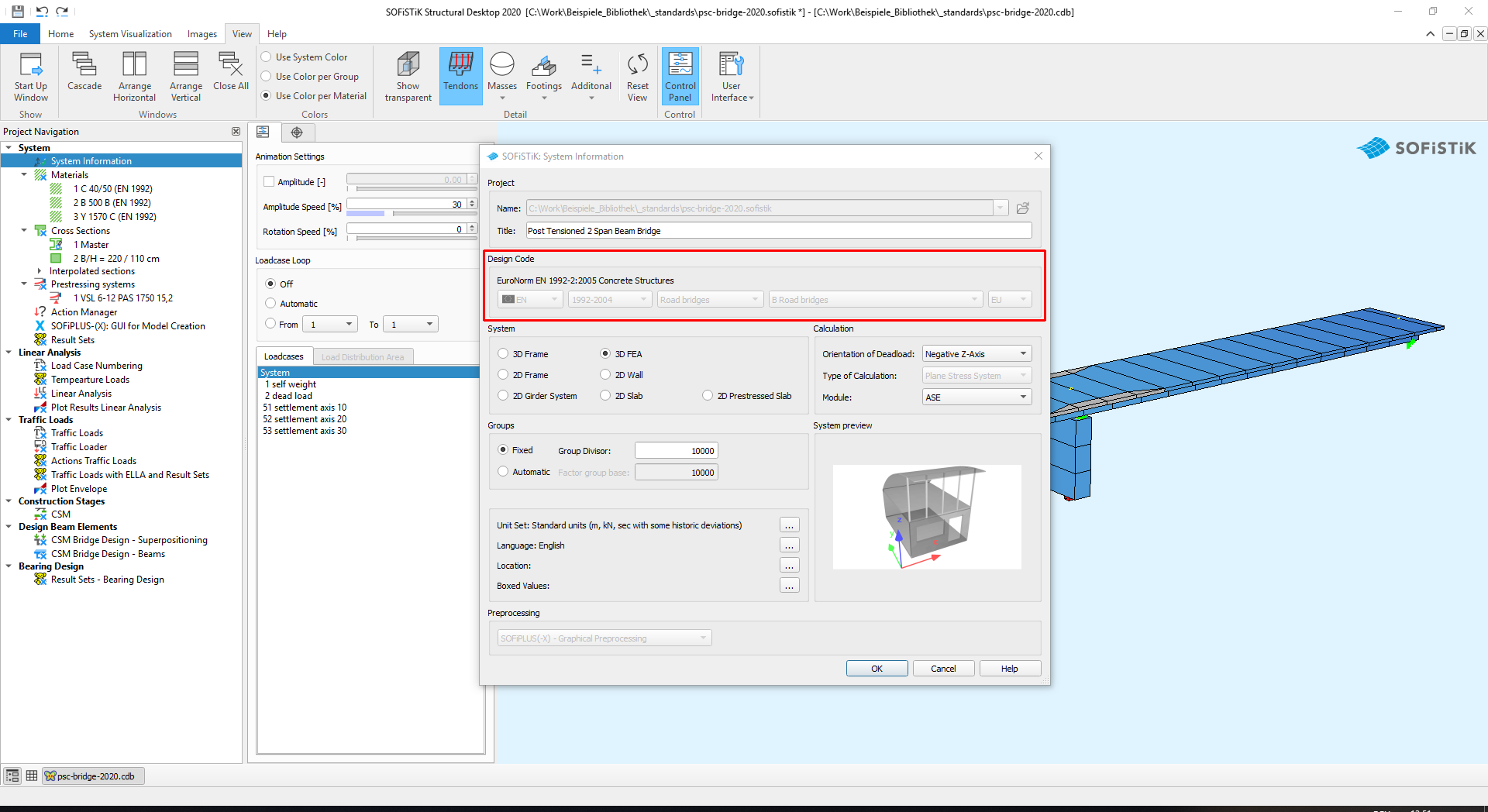
For bridge design we recommend to use a 3D system.
Material Definition#
Important
This is a general description, which can be different from the project discussed in specific tutorial. Please make the necessary adjustments by yourself.
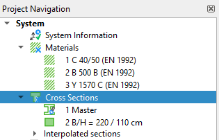
Inside the SSD task-tree the task Materials is one of the default settings.
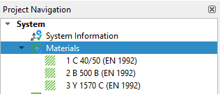
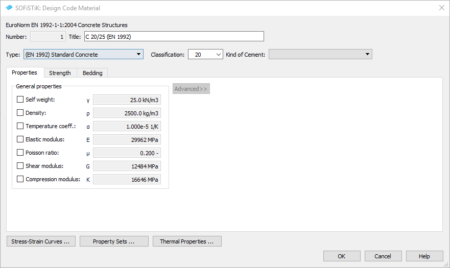
Simply use the right mouse click e.g. New Material from Design Code to generate a new material. You may repeat this command as many times as necessary.
Note
In case you have different construction stages in your cross section (e.g. composite section), it is necessary to define separate materials for every stage even if the material properties are the same for both parts.
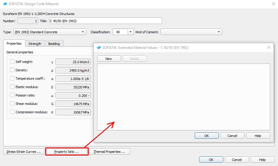
Extra material constants may be defined for any type of material (AQUA:MEXT record). Please refer to AQUA manual for more details:
Cross-section definition#
Important
This is a general description, which can be different from the project discussed in specific tutorial. Please make the necessary adjustments by yourself.
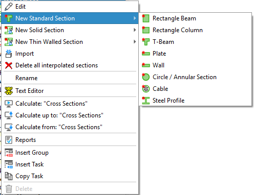
Inside the SSD task-tree the task “Cross Sections” is one of the default settings.
With a right mouse click on this task you open the context menu. Select the command New Standard Section and decide, which type of cross section you want to define.
The following standard cross sections are available:
Note
Simply use the right mouse click function to generate as many standard cross sections as necessary. Specific bridge cross sections will be generated later via SOFiPLUS - Cross Section Editor.
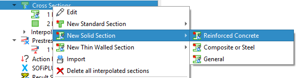
For user defined cross sections please use the cross section editor inside SOFiPLUS. You may select between a New Solid Section or a New Thin Walled Section.
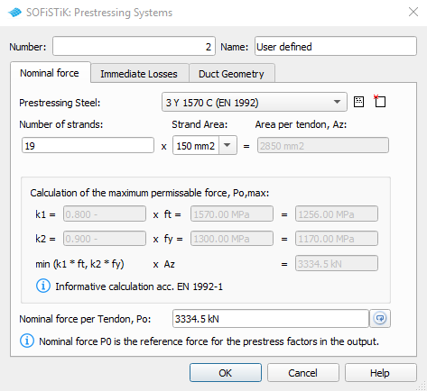
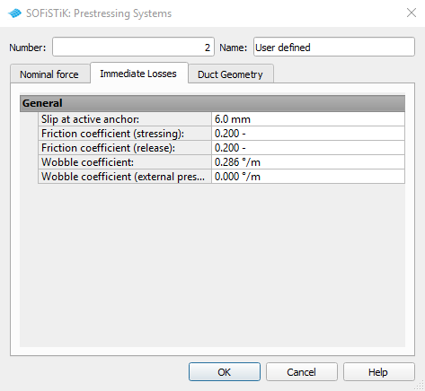
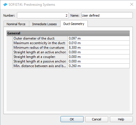
Prestressing System#
Important
This is a general description, which can be different from the project discussed in specific tutorial. Please make the necessary adjustments by yourself.
Please add a new SSD-task Prestressing Systems to your project. With a right mouse click on this task you open the context menu. Select the option New and generate a new prestressing system. Simply fill out all necessary information within the three tabs.
It is also possible to import prestressing systems from a different database. Simply use the right mouse click on the task and select the command Import.
Action Manager#
A new task called “Action Manager” will be added to our bridge project. Define all necessary actions for the bridge design in this task before starting to model the bridge within SOFiPLUS.
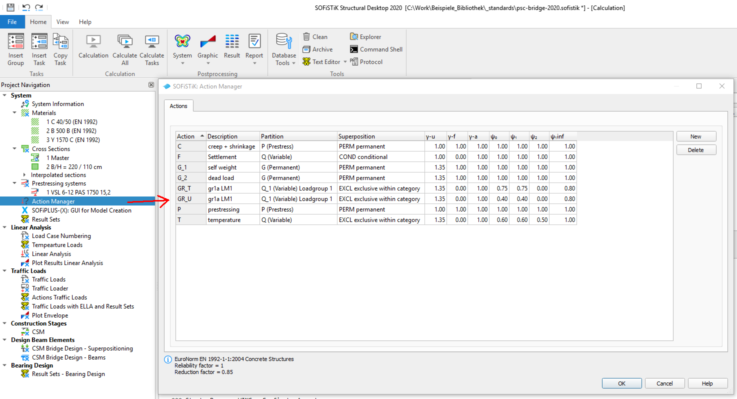
We recommend the following list of actions.
Description |
Action |
PART |
SUPP |
|---|---|---|---|
Self weight |
G_1 |
G |
PERM always |
Additional Dead load |
G_2 |
G |
PERM always |
Temperature |
T |
Q |
EXCL exclusive |
Settlement |
F |
Q |
COND conditional |
Traffic load TS |
GR_T |
Q_1 Load Group 1 |
EXCL exclusive |
Traffic loads UDL |
GR_U |
Q_1 Load Group 1 |
EXCL exclusive |
Prestressing |
P |
P |
PERM always |
Note
Action for Creep and Shrinkage will be defined later on inside the construction stage manager CSM
System Generation within SOFiPLUS#
Open SOFiPLUS from the SSD task SOFiPLUS(-X) GUI Model creation.
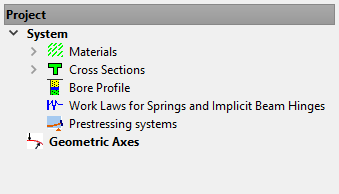
Inside the SOFiPLUS window all necessary commands are organised in a Sidebar on the left side. Tab “System” repeats the options from SSD to define materials, cross sections and prestressing systems. You also find the command to define new geometric axes.
Note
It may be useful to collect and write down all necessary project data before starting with the system generation. E.g.:
bridge geometry information including axes information
cross section geometry
construction sequence including influence on cross sections and bridge structure
concept for element group numbering. All elements such as beams, quads, springs, couplings are organised in groups.
Define Bridge Axis#
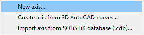
First we define a new bridge axis. Go to sidebar > tab “System” and use the right mouse click on the command “Geometric Axes”. From the possible commands we use the option “New Axis..”.
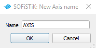
Now define a new name for your axis.
Warning
There are only 4 letters and/or numbers allowed for the axis name.
Confirm the name with “OK” and you will get into the first dialogue, where you define the horizontal alignment of the new bridge axis. Most important is to understand the concept of stations along the axis. Just imagine you start walking along the axis for 15.0 m and you started at station 10.0 m. Now you stop at station 25.0 m = 10.0 +15.0 m . For further description please see the SOFiPLUS manual.
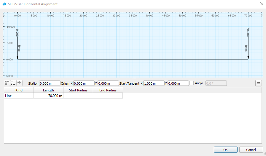
Note
We recommend to define your axis longer than your real bridge length. Usually an extension of 10.0 m at the beginning and > 10.0 m at the end of the bridge is sufficient. This is necessary to add bridge elements later on, because you are not allowed to use negative station values.
After the horizontal alignment you define the vertical alignment. Usually you can use the information from the bridge layout drawing.
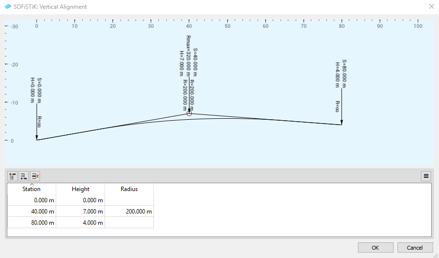
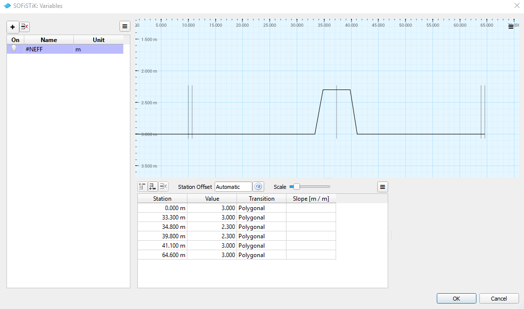
A very important option is to define variables along the bridge axis. These variables can be used for the cross sections generation later on. The idea is to define a master cross section with all necessary variables inside. During the meshing process the program will use cross section and variable information to generate all necessary interpolated cross sections for the final finite element mesh.
Warning
You are not allowed to use variable for material numbers inside the cross section. It is also not possible to use variables for the area of longitudinal reinforcement along the bridge axis.
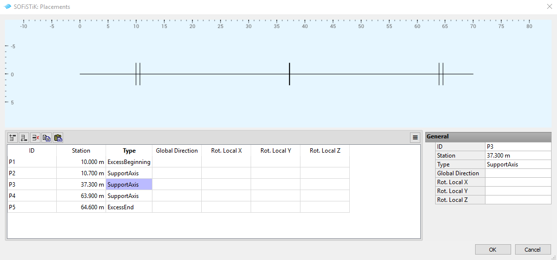
A next important step is to define placements along the bridge axis. Placements represent special points along the bridge axis to define supports, construction points, beginning and end of a bridge structure. We will use these placements later on for an easy and fast system generation with structural lines and structural areas. They are also very important for the influence line evaluation later on. Support placements will be used together with the cross members editor later on to generate support elements and align them automatically with the placements and the axis.
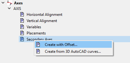
The last setting during the axis generation is the option to define secondary axes. Secondary axes can be used for grid structures to define the positions of multiple beams parallel to the bridge axis, or also for shell bridges to define the boundary of the bridge including the position where the shell thickness changes.
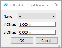
You do have two options to generate a scondary axis. With a right mouse click on the option “Secondray Axes” you have two options. The first one generates a secondary axis with a fixed offset in y and/or z direction. With the second option you can create a secondary axis from any AutoCAD 3D curve available inside your drawing.
Define Cross Sections#
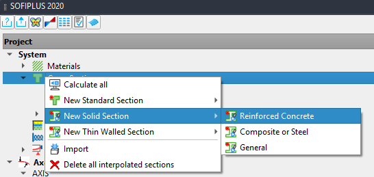
Besides the standard cross sections, we already defined inside the SSD, we will now define more complex bridge cross sections. This will be done within the Cross Section Editor inside SOFiPLUS. First go to the “System” tab and use the right mouse click on “Cross Sections” . For example we can define a new solid cross section for reinforced concrete.
Note
You will find detailed descriptions and videos, how to use the cross section editor, in our bridge tutorials.
Define Bridge Geometry#
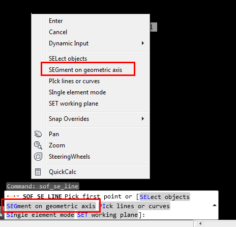
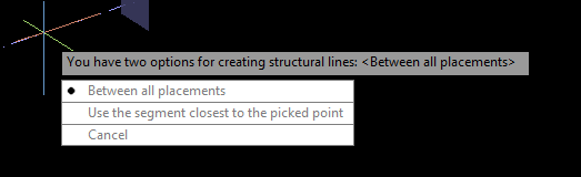
Whether you will use beam or shell elements, defining the bridge geometry follows the same principles based on an existing bridge axis. Go to the tab “Structural Elements”and select a command “Line” or “Area”. Use the right mouse click to open the context menu and select the command “SEGment on geometric axis”. Now click on the axis in your drawing area. The next context menu opens. Select the command “Between all placements”. The program will automatically generate structural elements between all predefined placements.
For more detailed information please see the different bridge tutorials.
Define Tendons#
The tendon geometry and the tendons will be defined graphically inside SOFiPLUS. There are two general options to define tendons inside SOFiPLUS:
with “PT Editor” based on bridge axis
with “Tendon (Draw)” command based on existing AutoCAD spline or line objects.
Note
In case you do have multiple beams you should use secondary axes to define the beam elements and also to define the tendon geometry.
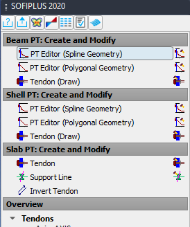
For new bridges the “PT Editor” is the most useful command, we recommend to use. Simply go to the sidebar tab “Prestressing” and select the command “PT Editor (Developed Geometry)”. Please be careful according to the elements you are using inside your system. In case of beam elements you must use the command below the title “Beam PT: Create and Modify”.
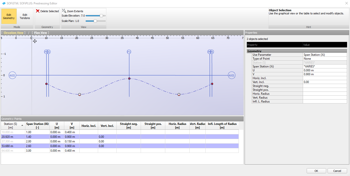
In the next step you must select a geometric axis as a reference. Inside the upcoming dialogue all settings for the tendon geometry and the tendons are defined according to the selected bridge axis. The general principle is to define one tendon geometry and use this geometry to define multiple tendons if necessary with different start and end stations for every single tendon. The tendon geometry is a spatial spline defined by several Geometry Points. Inside the table of Geometry Points you may edit every setting. Alternatively you may select multiple points and change the settings of all selected points inside the Properties field.
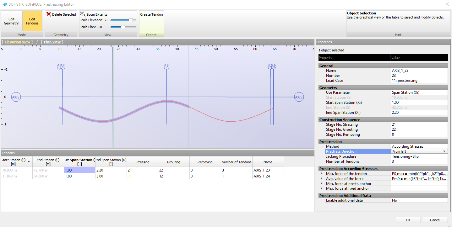
Clicking on the “Edit Tendons” button you get into the Tendon definition dialogue. The first tendon is already set inside the table. With the button “Draw Tendon” you may define new tendons with variable start and end stations. Important is to define a load case for the static determinant tendon forces and moments. Usually we recommend to have the necessary load cases defined before you start defining the tendons. Nevertheless it is also possible to generate a new load case right from this dialogue. In case you define a load case (LC0) the static determinate forces and moments are saved separately inside this load case. Usually this input is not necessary. The CSM procedure, described later, will automatically take care of the two parts of the prestressing forces and moments.
After defining all tendons you see a list of all tendons in the sidebar. In case you want to define new tendons, which are parallel to your already defined tendons, you may use the command “Clone…”, or “Copy…” from the context menu. Simply use the right mouse click on any “Tendon geometry”. In case you want to clone a tendon geometry, the new ones have a fixed offset in y- and z-direction related to the connected bridge axis. In the other case, you make a copy with the ability to edit all properties.
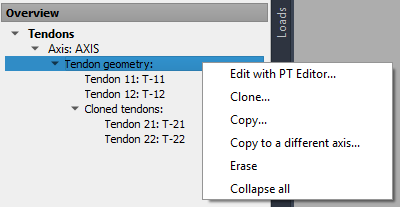
In case you want to edit the tendon properties simply double click on the tendons listed in the sidebar.
Note
Editing the cloned tendon geometry is not possible.
Now the tendon generation process is finished.
Define Load Cases#
We recommend the following list of load cases. All these load cases are defined inside SOFiPLUS > Loadcase Manager tab “Loadcases”.
Basic Loads
LC Number |
Description |
Action |
|---|---|---|
1 |
self-weight structure |
NONE |
2 |
additional dead load (e.g asphalt) |
NONE |
51-5X |
settlement in every support axis, e.g. 10 mm |
F |
81-82 |
uniform temperature load |
NONE |
83-84 |
temperature difference |
NONE |
91-98 |
temperature combinations delta TN + wm*delta TM and wn*delta TN + delta TM |
T |
Note
The load cases 1 and 2, self weight and additional dead load, will be used later on inside the construction stage manager (CSM). Processing the construction stages, the load cases will be connected automatically to the corresponding action types. Connecting LC 1 and 2 to action “NONE” will secure, that they will not be used twice in a manually defined combination later on.
According to the code, a combination of temperature loads is necessary. This will be done in a separate user task .
Traffic Loads
LC Number |
Description |
Action |
|---|---|---|
120x |
load train e.g. LM1 with 300 kN axle load |
NONE |
2xx |
envelope from “Traffic Loader”, TS Load Group 1 |
L_T |
3xx |
envelope from “Traffic Loader”, UDL Load Group 1 |
L_U |
Define Loads#
For defining loads, you may follow two general principles:
Element Loads
Free Loads
Element loads are directly related to a structural point, line or area. In case the geometric properties of these elements changes, the load changes as well. As we are defining our bridge system according to a bridge axis, we also want our loads to follow the axis, in case we change the axis parameters of our bridge. For that reason we recommend to use “Element Loads” for bridge design.
The “Free Loads” are based on the geometric input. Later on, during the meshing process, the loads will be connected to existing elements. In case no element can be found also no loads will be applied.
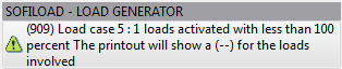
Note
If any load is not fully applied to the elements, there will be a warning:
Mesh System#
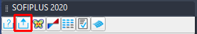
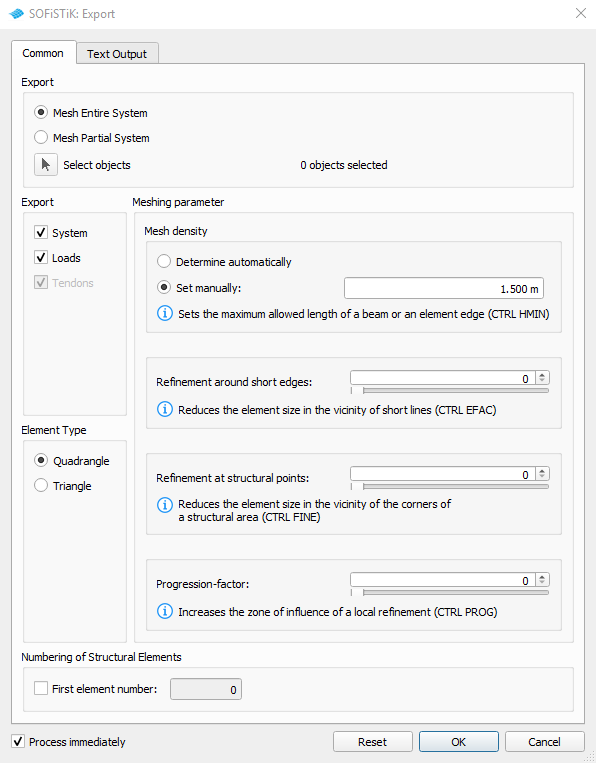
To start the meshing process click on the export button on the top left of the sidebar.
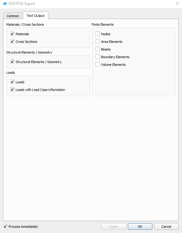
The export dialogue contains two tabs: “Common” and “Text Output”. Usually the default settings are sufficient and you simply click “OK” to start the automatic mesh generation. The settings inside the tab “Text Output” control the amount of output. The standard rule in SOFiSTiK is, that the maximum amount of output is based on the settings before any calculation. Later on it is possible to reduce (or increase again) the existing output in the documentation (Report). But you cannot increase a non-existing output without a new calculation.
Now the input is finished and we can go back to the SSD window. Usually you may close the SOFiPLUS window.
Linear Analysis#
Before we start analysing all existing load cases, we have to create combined temperature loads.
Combination of Temperature Loads#
Temperature loads will be combined according to the requirement of the code later on in the SSD project, with a task “User Text”, because this is very easy to do numerically.
The input sequence is printed below:
+PROG SOFILOAD
HEAD Temperature Load Combinations
$ Load combinations
LC 91 TYPE T TITL 'T summer posdt TN+wm*dT' ; COPY 81           ; COPY 83 FACT 0.75
LC 92 TYPE T TITL 'T summer negdt TN+wm*dT' ; COPY 81           ; COPY 84 FACT 0.75
LC 93 TYPE T TITL 'T winter posdt TN+wm*dT' ; COPY 82           ; COPY 83 FACT 0.75
LC 94 TYPE T TITL 'T winter negdt TN+wm*dT' ; COPY 82           ; COPY 84 FACT 0.75
LC 95 TYPE T TITL 'T summer posdt wn*TN+dT' ; COPY 81 FACT 0.35 ; COPY 83
LC 96 TYPE T TITL 'T summer negdt wn*TN+dT' ; COPY 81 FACT 0.35 ; COPY 84
LC 97 TYPE T TITL 'T winter posdt wn*TN+dT' ; COPY 82 FACT 0.35 ; COPY 83
LC 98 TYPE T TITL 'T winter negdt wn*TN+dT' ; COPY 82 FACT 0.35 ; COPY 84
END
Task “Linear Analysis”#
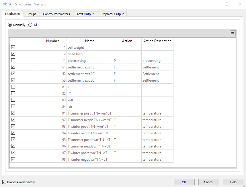
For the linear analysis we add the task “Linear Analysis” to our project file. When opening this task all available load cases within the database are selected for analysis. As we do have self weight, additional dead load and the single temperature loads in our database, but we don’t want to have them used in our project we change the selection manually.
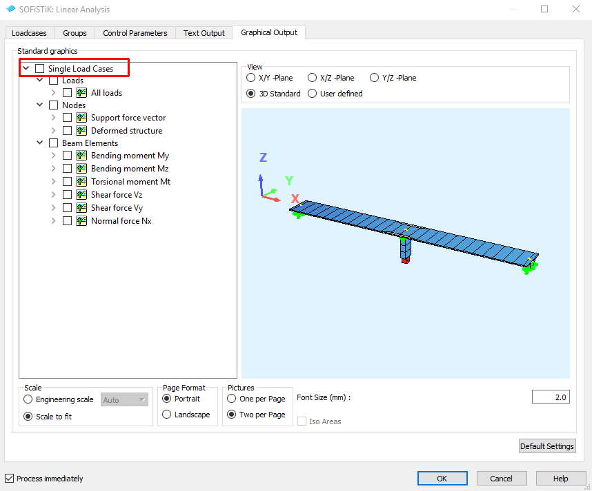
In every SSD task there is a tab “Graphical Output”. These pictures are designed for a simple 2D slab project. Therefore we recommend to switch of all standard graphics. We will generate our own graphics in a separate task called “Interactive Graphic”.
Traffic Loads#
In SOFiSTiK you have two possibilities to calculate the traffic loads of your bridge:
You can define the traffic loads on your bridge and calculate them with the task Linear Analysis. For this approach it is usually necessary to define many load cases for the individual load positions on the bridge and superpose them. This option is used in the tutorial examples
Concrete Slab Bridge
Composite Bridge
For a detailed explanation of the procedure take a look at the description in the individual examples.
You can use the task
 Traffic Loader, which calculates the results for the traffic on your bridge based on the evaluation of influence lines.
This option is shown in the tutorial examples
Traffic Loader, which calculates the results for the traffic on your bridge based on the evaluation of influence lines.
This option is shown in the tutorial examplesPost Tensioned Concrete Beam Bridge
Balanced Cantilever Bridge
For detailed information about the task take a look at its description in our online help.
Important
The evaluation of influence lines with the traffic loader is based on the stiffness matrix of the system. This is only available if a linear analysis has been carried out. Please make sure that you have calculated at leat one loadcase with the Linear Analysis task, before using the traffic loader.
Construction Stages#
With the task ![]() Construction Stages we are able to analyse the whole building process.
In general this process will affect the forces and moments inside the structure and cannot be neglected.
Especially when having prestressed or composite structures the CSM is mandatory.
Construction Stages we are able to analyse the whole building process.
In general this process will affect the forces and moments inside the structure and cannot be neglected.
Especially when having prestressed or composite structures the CSM is mandatory.
Before adding the SSD task from the task library, you should set up a time line with all important incidents. These can be:
changes in the structural system (e.g. adding or removal of structural elements or changing of cross-sections)
the stressing or removal of tendons
the application of loads during the construction process (e.g. additional dead loads, loads related to formwork, etc.)
Stages must also be defined for the time intervals, where creep and shrinkage happens.
Important
Construction stages need also to be defined for cross sections with in-situ concrete additions and for tendons. This must be done in the Cross Section Editor and the Prestressing Editor in SOFIPLUS(-X) before running the Construction Stages task.
A detailed description of how to use the Construction Stages task can be found in our online help. There you will also find our recommendations for the numbering of construction stages and an overview of the results created by the task. For typical settings for certain bridge types please take a look at the individual tutorial examples.
Combinations and Superpositioning#
For the design process a combination of results in ULS and SLS states is necessary. To apply the automatic generation of all necessary combinations, add a task “CSM Bridge Design - Superpositioning” inside your project. Besides the default selection of actions like GR_T, GR_U, you need to select the variable actions you want to take into account for superpositioning and design. Permanent actions are considered automatically based on the results of the Construction Stages task.
For a description how to use the task and information about the created loadcases take a look at our online help.
Design Checks#
In SOFiSTiK there are several ways to carry out the design checks depending on the kind of bridge (reinforced concrete, prestressed concrete, steel, composite) and how it is modeled (beam elements, shell elements, hybrid model).
All these approaches are based on the results from the Construction Stages tasks and the design envelopes that are created by the task CSM Bridge Design - Superpositioning.
Please take a look at the individual tutorial examples to find out how to carry out design checks for your individual bridge type.
The following list gives an overview of examples with explanation of design checks
Post tensioned concrete bridges (checks for beam elements): Post Tensioned Concrete Beam Bridge
Reinforced concrete bridges (checks for shell and beam elements): Concrete Slab Bridge
Composite bridges (checks for beam elements): Composite Bridge
Generate Report#
In SSD, every single task produces a report file project_xx.plb. For a graphical visualisation of all results we recommend to add several tasks “Interactive Graphic”. You may move these tasks at any place inside your task-tree. Usually it is helpful to have system plots, plots with the resulting forces and moments and finally some plots with the design results.
Note
In every task “Interactive Graphics” you may define as many pictures as you want. Lots of pictures may slow down the performance. Therefore we recommend to use multiple tasks for graphical results.
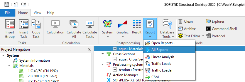
There is an option to generate a complete documentation file. Go to SSD ribbon tab “Home” > “Report”.
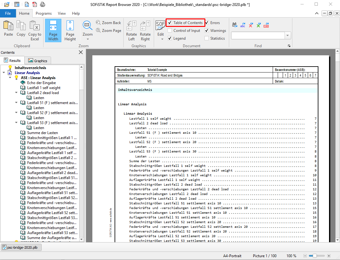
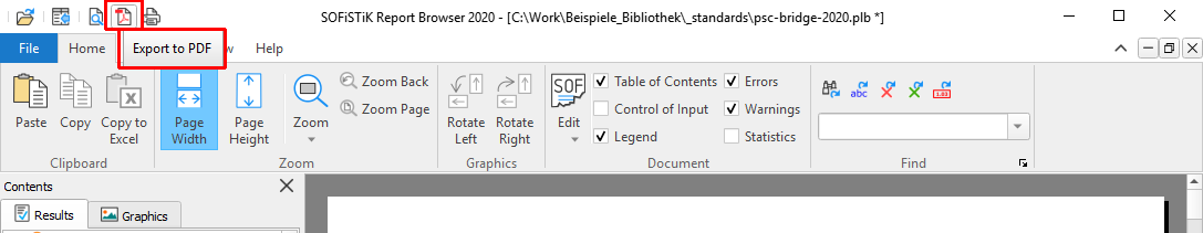
Inside the complete document you may insert a table of contents. This can be done inside the Report Browser ribbon tab “Home”. Simply mark the option “Table of Contents”, see picture below.
To have a secure output file we recommend to print the final document to a pdf file. This can be done easily with the print function from the Report Browser. Open the Report Browser and go to menu “File” > “Export to PDF”
Save Project Files#
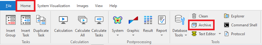
After the project is finished, all calculations are done and a final report was generated, you should save your project on a company server. For that reason we recommend to pack your project files together in one project.zip file. Simply go to SSD ribbon tab “Home” > “Tools” and use the button Archive.
Note
To reproduce a project, only the files project.sofistik and project.dwg are necessary.