Non-Linear Cracked Analysis (detailed)#
In cases where a more realistic cracked behaviour is required, a non-linear analysis can be performed but requires a finer setting of certain parameters. This method will be applied differently depending on the goal of the analysis, which can include:
the study of a structure with fixed reinforcement levels
the design of a new structure, where required reinforcement is an output of the design.
The way the reinforcement is defined in each of these 2 distinct cases differs within the software.

Order of tasks performed for non-linear analyses.#
In the Example Files#
In the example files, this cracked non-linear analysis is performed by tasks of group Non-Linear Cracked Analysis (detailed). The results of this detailed cracked analysis are saved in the following load and design cases:
To Generate a Custom Reinforcement Distribution in the Slab |
||
Type |
Nr |
Description |
Load Case |
9999 |
Dummy Combination of Results necessary to generate a Design Case containing a Custom Reinforcement Distribution |
Design Case |
99 |
Custom Reinforcement Distribution in the Slab |
For an Analysis Based on the Reinforcement Distribution from the Uncracked Linear Design (DC15) |
||
Type |
Nr |
Description |
Load Case |
3500 |
SLS Combination of Loads for Cracked Analysis and Design (detailed), Non-Linear |
Design Case |
35 |
SLS Reinforcement Distribution in the Slab according to the Cracked Design (detailed, Non-Linear) |
For an Analysis Based on the Custom Reinforcement Distribution (DC99) |
||
Type |
Nr |
Description |
Load Case |
3600 |
SLS Combination of Loads for Cracked Analysis and Design (detailed), Non-Linear |
Design Case |
36 |
SLS Reinforcement Distribution in the Slab according to the Cracked Design (detailed, Non-Linear) |
Prerequisite Knowledge#
Combinations in Non-Linear Analyses#
When performing a non-linear analysis, it is essential to distinguish between combination of loads, combination of results and envelopes.
Combine Results and envelopes (SSD’s task Superpositioning for Combination Rules) use the results from linear analyses and combine these with relative factors in order to output values for designs and checks. These values can not be used in non-linear analyses.

Order of tasks performed for linear analyses.#
A combination of loads is what is needed in the case of non-linear analyses. In such case, a new load case is generated, using single load cases factorised according to the user’s input (e.g. following combination rules from the norm).
Order of tasks performed for non-linear analyses.#
For non-linear analyses, the task Combine Loads should be used. There, the necessary ULS and SLS combinations of loads for the project are defined. Then, these combinations of loads are available to perform non-linear analyses using e.g. SSD tasks Analysis of Combined Loads or Non-Linear Analysis SLS.
See also
Refer to the online documentation of SOFiSTiK FEA for more information on the task Combine Loads.
Input Reinforcement Distribution for Non-Linear Analyses#
To perform a non-linear analysis, it is necessary to provide an input reinforcement distribution (position and amount of reinforcement) in the QUAD elements. In the graphical task used in this tutorial, the input reinforcement distribution must be provided as a design case. The following paragraphs describe two methods to obtain this design case.
Input Reinforcement Distribution from a Previous Design
Typically, the input reinforcement distribution of a non-linear analysis is calculated by the software as the required amount of reinforcement from a previous design step and already available in a known design case (e.g. from an uncracked analysis and design calculation).
See also
Please refer to the Beginners Tutorial - Design of Concrete Building for a complete description of the workflow on how to perform a linear analysis and design, obtain and save required reinforcement distributions from it.
Custom Input Reinforcement Distribution
In some cases, it maybe necessary to provide manually a fixed layout and amount of reinforcement in the QUAD elements, which the software should not modify. This is for instance convenient to re-calculate exisiting buildings.
To achieve this, the following procedure, can be followed (illustrated in the examples files by tasks in sub-group Generate a Custom Reinforcement Distribution):
With task Design Parameters of Area Elements or a corresponding text input for module BEMESS, enter the wished layout and amount of reinforcement in the QUADs using the design parameters.
With task Combine Results, create a new dummy combination of results corresponding to very little loading. For this, factorise the results of the selfweight load case with a very small factor (eg. 0.01).
With task Design ULS (Area Elements), perform on the dummy combination of results a linear ULS design as usual. This way, the software will save the rebar distribution defined in step 1 in the chosen Design Case.
Attention
When defining manually the layout and amount of reinforcement for the Custom Reinforcement Distribution, the wished amount must be provided both as minimal and as maximal reinforcement value. This intructs the software that this quantity is fixed, and prevents it from adjusting the reinforcement automatically during the design.
Note
Defining carefully the design parameters of the area elements in the project is a key aspect to obtain inital reinforcement distributions of good quality before performing non-linear analyses. This definition is done according to groups. It is therefore important to carefully assign group numbers when modelling the system.
If the modelling has already been finalised and it is not practical to change the general geometrical definition of structural elements, the Attribute Areas allow to locally change properties. They can be used to change or add group assignation and hence modify or add rebar zones.
Input Reinforcement Distribution#
Before performing the non-linear analyses, an input reinforcement distribution must exist. In the example files, two different methods illustrate how to obtain such distributions. Therefore, two design cases, each storing an input reinforcement distribution, are used:
Design Case 15 stores the Reinforcement Distribution calculated by the software during the uncracked SLS design.
Design Case 99 stores the Custom Reinforcement Distribution provided manually. Tasks of sub-group Generate a Custom Reinforcement Distribution show how to generate and store a Custom Reinforcement Distribution in a chosen Design Case.
Attention
To avoid convergence issues in the non-linear analyses, it is recommended to provide as input reinforcement distribution a design case where there is a minimum reinforcement value defined for each QUAD and each reinforcement layer.
Combination of Loads#
The Task Combine Loads is used to create manually the load combinations necessary for the non-linear analyses. With this task, a quasi-permanent SLS load combinations are generated for each input reinforcement distribution. These load combinations are saved in load cases:
3500 (SLS) for the non-linear analysis using as input reinforcement the Reinforcement Distribution from the uncracked design (DC15).
3600 (SLS) for the non-linear analysis using as input reinforcement the Custom Reinforcement Distribution (DC99).
After calculating these tasks, the combined loadings on the slab is available and can be displayed for load cases 3500 and 3600. Analyses for these load cases have not yet been conducted, so not results is available yet.
Design Parameters#
Before performing the non-linear analysis and design, the design parameters of QUAD elements should be checked. This can be conducted with the graphical task Design Parameters of Areas Elements. However, this task can be placed only once in the project navigation. In the example files, a text input task is used instead of the graphical one. This allows to modified and reset successively this parameters to illustrate the different design methods in the same project file.
The text task contains input for module BEMESS, which defines the same design parameters for all QUAD elements in the project.
It sets explicit values for the concrete cover (GEOM), the reinforcement direction (DIRE), the rebar diameters (PARA)
and the minimum reinforcement (PARA) while leaving all other parameter values to their default:
+PROG BEMESS
HEAD Default Values of Slab Design Parameters

GEOM HA 35 DHA 10 HB 35 DHB 10
DIRE UPP 0 LOW 0
PARA DU 10 DU2 10 DL 10 DL2 10 ASU 1.13 ASU2 1.13 ASL 1.13 ASL2 1.13

END
See also
Please refer to:
the online documentation of SOFiSTiK FEA, Task Design Parameters of Area Elements
to know more about design parameter of area elements.
Non-Linear Analysis#
To investigate long-term deflections of slabs with a non-linear analysis, task Non-Linear Analysis in SLS is available.
Selection of Load Cases and Reinforcement Distributions#
Opening the task, load cases for which a SLS non-linear analysis can be performed are available for selection. These load cases are all combinations of loads of type SLS present in the project.
Tip
Performing a non-linear analysis may be long, as each combination of loads is analysed individually. When performing an initial calculation to set up the non-linear iteration parameters, it is recommended to start with a small number of selected combination of loads and to select all required combinations only after the parameters are set.
Once the necessary combinations of loads have been selected, the input and calculated reinforcement distributions should be provided.
In the example files, the following combinations and design cases are used:
Combination of Loads |
Input Reinforcement |
Non-Linear Analysis Type |
Calculated Reinforcement |
Load Case 3500 |
Design Case 15 (from uncracked design) |
SLS |
Design Case 35 |
Load Case 3600 |
Design Case 99 (Custom Reinforcement Distribution) |
SLS |
Design Case 36 |
Attention
Task Non-Linear Analysis in SLS allows to perform a non-linear analysis, calculating long term deflections of slabs, while checking an existing (input) reinforcement distribution.
The amount of reinforcement in the slab is not modified by the analysis!
Hint
The calculated reinforcement distribution, which number can be provided in the dialogue, is equivalent to the input reinforcement. It only stores the reinforcement values differently to meet the requirements of non-linear analyses. For instance, it also stores reinforcement values at the Gauss Points of QUADs.
In summary, the calculated reinforcement distribution allows a graphical check of the reinforcement applied by ASE for the non-linear analysis.
Definition of the Type of Non-Linearity#
Finally, we define the type of non-linearity to account for this analysis run and their parameters. Several settings are available to define the type of non-linearity:
Option Nonlinear Spring is always active. It shows that all springs, cables or beddings for which non-linear properties are available in the project will be calculated non-linear.
Option Lifting edges make the slab’s supports work only in compression. If a support node experiences tension, the software will deactivate this support point. It is not necessary to define non-linear supports to activate this option.
Option Cracked concrete activates non-linear material properties and worklaws for the QUAD elements.
When the non-linear QUADs are active (Cracked concrete), each QUAD element is subdivided into layers (by default 10). At each step of the non-linear analysis, stresses are calculated for every layer’s boundary and then integrated over all layers to determine the internal forces. After this all, the forces in the reinforcement, including the tension-stiffening-effect are added. Finally an independent check is made for the plate’s shear stresses.
In the dialogue, options are available to control the material properties used in the analysis run. Especially, it is possible to control the effects of aging of the concrete with:
the creep factor
the shrinkage coefficient
Moreover, it is possible to override temporarily:
the maximal tensile strength for tension stiffening
the maximal tensile strength in pure concrete layers (layers where no reinforcement is present)
the limit shear stress (in tab Control Parameters)
By default, the software uses the properties set the materials definitions.
Note
Task Non-Linear Analysis in SLS only calculates a non-linear material behaviour for the QUAD elements. Linear (BEAM) Finite Elements, if present in the project, will behave linearly. Nevertheless, it is possible to use the factor Stiffness of beams to reduce the stiffness of all BEAM elements for this analysis run. This allows to apply a reduced (cracked) stiffness for all BEAMs. By default, a reduction to 60% of the full stiffness (Stiffness of beams = 0.60) is applied.
See also
Please refer to manual of module ASE, Chapter 2.12 Non-Linear Analysis of Plates and Shells for a detailed explaination of the non-linear effects available and their implementation for QUAD elements.
In the example files, the Cracked Concrete option is active to investigate the cracked behaviour of the slab. Other material properties and settings are left to their default values.
Results of Non-Linear Analyses#
After calculating the task, non-linear analysis results are available and can be displayed for load cases 3500 and 3600. For instance, the following results are available in:
Graphics - the displacement of the slab can be displayed.
Graphics - for each QUAD element, the maximum non-linear strains in the concrete and in the reinforcement can be displayed.
System Visualization - by selecting a QUAD elements for load case 3500 or 3600, the non-linear stresses in the different QUAD layers, incl. reinforcement, are displayed.
the calculation Report - exact material worklaws (concrete, reinforcing steel) used in the analysis are printed out and a complete statistics of non-linear effects (calculated max. concrete compression strain, max. reinforcement steel stress etc.) is available.
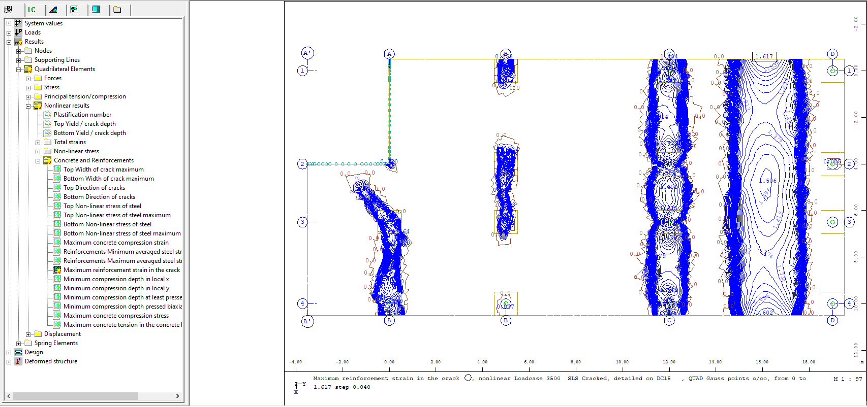
Non-linear strains in the reinforcing steel of the cracked QUAD elements in Graphics.#
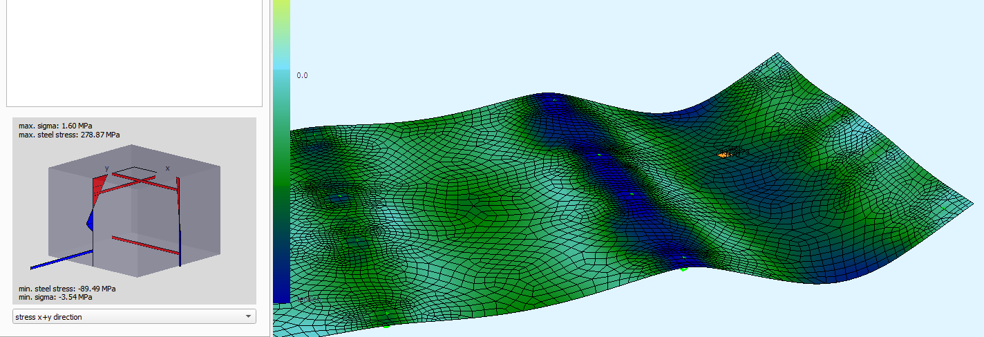
Distribution of non-linear stresses in the different layers of a cracked QUAD element in System Visualisation.#
Convergence of Non-Linear Analyses#
A non-linear analysis is always an iterative process which should converge toward an equilibrium (small residual force, stable energy value…). If this is not the case, the software will return warning and error messages. Several aspects can lead to convergence issues (no minimum reinforcement, stresses/strains exceeding the materials’ limits etc.) and simply increasing the number of iteration may not always be enough to reach convergence. Even when no convergence was reached, results are available and help understand which aspect is problematic. Especially, if the convergence issue is linked to exceeded material strain or stress limits, the non-linear strains and stresses available in Graphic allow to identify the overloaded QUAD elements.
See also
For more details and support regarding convergence issues, please refer to manual of module ASE, Chapter 2.12.8 Miscellaneous Information. Iteration Control - Improvement of the Convergence. There, detailed information is available about convergence issue, its diagnosis and its solutions.
To Go Further#
Task Non-Linear Analysis in SLS is optimized to investigate long-term deflections of slabs with a non-linear analysis while checking the reinforcement distribution provided as input. Many more possibilities are available in SOFiSTiK when it comes to non-linear calculations. Converting the graphical task in a User Task and adjusting the text input is an easy method which allows to access other use cases. For instance, the task Non-Linear Analysis in SLS:
always uses the Service Nominal non-linear worklaw (without material safety factor). The other types of worklaw can also be used in non-linear analyses by adjusting the record
NSTR.never modifies the reinforcement distribution. A non-linear analysis which increases the amount of reinforcement when specific stress values are exceeded is possible using record
REIQ(see the manual of module ASE, chapters 3.18 Reinforcement in QUAD Elements).is dedicated to the non-linear analysis of reinforced concrete QUAD elements. Non-linear calculations are also available for other materials (non-reinforced concretes, fiber-reinforced concretes etc.). Several Teddy examples provided with the software are covering these topics.
Evaluation of Results and Additional Resources#
Further information about the evaluation of results and additional resources is common to both methods of this tutorial: Evaluation of Results.