Analysis of Cracked Concrete Slabs#
Introduction#
This tutorial illustrates how to perform the analysis of cracked reinforced concrete surfaces with SOFiSTiK.
A cracked concrete analysis and design requires a more comprehensive approach in comparison to an uncracked concrete state due to inherent material non-linearity. An inclusion of the cracking effects into the analysis is often required for a wide selection of engineering problems, ranging from the analysis of the existing structures to an industrial tank design.
As shown below, two methods are available to perform a cracked concrete analysis in SOFiSTiK:
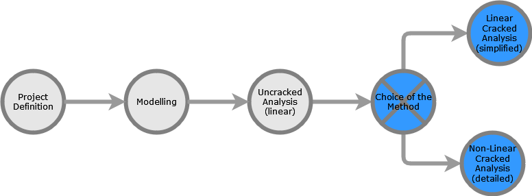
SOFiSTiK workflow highlighting the two methods available for the analysis of cracked concrete.#
Linear Cracked Analysis (simplified) simulates the behaviour of the cracked concrete. For this type of analysis, the impact of cracking is approximated by manually modifying the material properties, which remain constant throughout the analysis regardless of stress levels.
Non-Linear Cracked Analysis (detailed) uses an iterative process to evaluate the behaviour of the structure in the cracked condition. It accounts for material non-linearities (worklaw).
Both methods allow to determine the deformation of concrete structures in a cracked state as well as further results such as the accompanying material stress levels. Detailed theoretical information regarding how the non-linearity is implemented in SOFiSTiK can be found in the manual of module ASE, at chapters 2.11 Non-linear Analyses and 2.12 Non-linear Analysis of Plates and Shells.
Modelling Insights and Tips#
The workflow to perform cracked analysis in SOFiSTiK is always the same and independent of the pre-processor. Therefore, any modelling platform supported by SOFiSTiK is appropriate. The choice of the modelling platform can be guided solely by your other project’s requirements.
To illustrate this tutorial, two example files are available:
Autodesk Revit file modelled with the application SOFiSTiK Analysis + Design.
Autodesk AutoCAD file modelled with the application SOFiPLUS.
While preparing a structural model for the project where a cracked concrete analysis is anticipated, particular attention should be paid to assigning structural elements to the SOFiSTiK Groups.
A correct group numbering will allow to:
Define rebar distributions in detail
Modify material and/or stiffness properties of elements
Assign factors and parameters to control the behaviour of elements
Visualise parts of the structure more easily e.g. using filters
In the example files, the elements of the concrete slab are assigned into two groups. Group 150 contains all QUAD Finite Elements in the vicinity of the point supports of the slab. Group 100 contains all other QUAD Finite Elements of the slab.
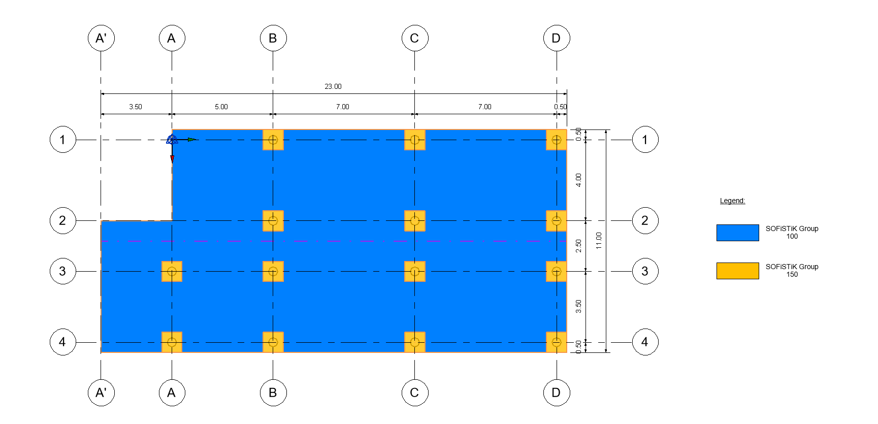
Group assignation in the slab.#
Tip
In SOFiPLUS, the Assign Group command allows to manage efficiently the assignation of elements to SOFiSTiK Groups.
In SOFiSTiK Analysis + Design (Revit), the SOFiSTiK Structural Properties panel allows to assign elements to SOFiSTiK groups.
Uncracked Analysis and Design#
Before a cracked analysis, the uncracked behaviour of the system should be known by conducting first a linear analysis and design.

Order of tasks performed for linear analyses.#
In the example files, this is performed by tasks of group Uncracked Analysis and Design (linear). The results of this uncracked analysis are saved in the following load and design cases:
Type |
Nr |
Description |
Load Case |
1 |
Linear, Results under the Selfweight |
Load Case |
2 |
Linear, Results under Live Loads |
Load Case |
1000 |
ULS Combination of Results for Uncracked Analysis and Design (linear) |
Load Case |
1500 |
SLS Combination of Results for Uncracked Analysis and Design (linear) |
Design Case |
10 |
ULS Required Reinforcement Distribution in the Slab according to the Uncracked Design |
Design Case |
15 |
SLS Required Reinforcement Distribution in the Slab according to the Uncracked Design |
See also
Please refer to the Beginners Tutorial - Design of Concrete Building for a dedicated example on how to perform an uncracked, linear analysis and design of concrete slabs.
Cracked Analysis and Design#
Evaluation of Results#
At the end of a non-linear analysis, all results are stored in the database and are accessible via the post-processing tools of SOFiSTiK:
Report Browser for the direct output of the calculations
Result Viewer for tables and plots
Graphic for diagrams
With these tools, the results can be evaluated according to the project’s objectives and the normative requirements.
Tip
For the visualisation of deformation, the display of nodal displacement in Graphic is one of the most suited options. However, the question arises whether a limit deformation has been reached.
This check can be conducted by changing the settings of visualisation:
For a visualisation with isolines, in the tab Isoline, set a limit value at the desired value
For a visualisation with isosurfaces, in the tab Filing, set colours with single values corresponding to the desired levels.
Additional Resources#
Further help and support about cracked and non-linear analysis of slabs can be found here:
The manual of module ASE
More detailed theoretical information regarding how the non-linearity is implemented in SOFiSTiK can be found in the ASE module manual, chapters 2.11 Non-linear Analyses and 2.12 Non-linear Analysis of Plates and Shells.
The Workshop Video ASE Non-Linear Shells, Cracked Concrete, Steel
Please accept marketing cookies to watch this video.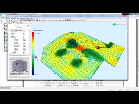
Note
This video was recorded using SOFiSTiK 2016. When performing the procedures, you may notice differences in functionality and user interface.