Cross Section of Reinforced Conrete - Definition of Air Contact Ratio for the Calculation of Creep and Shrinkage#
Introduction#
This document provides some explanations for the definition of the air contact ratios for a concrete cross section with the program AQUA or the Cross Section Editor.
Theoretical Background#
For a calculation of creep and shrinkage the information about the air contact ratio is necessary at the edges of the solid cross section. The air contact ratio for an edge can be different depending on the construction stage of the solid cross section.
With the information about the air contact ratios of the cross section edges the program AQUA calculated an effective depth deff which is used in a later calculation for creep and shrinkage.

where: A - area of the cross sectional polygon, U - length of the periphery which has air contact
Default Settings of the Program AQUA#
The program AQUA has following default settings:
polygon as boundary - air contact ratio with factor 1 for ventilated
polygon as opening - air contact ratio with factor 0 for not ventilated
If an edge of the solid cross section is ventilated in the first construction stage and not ventilated on a second construction stage due to an additional cross section part, the program AQUA recognizes it automatically. Using the default settings in the cross section definition it is not necessary to define the air contact ratio explicitely at the concrete material.
Definition of the Air Contact Ratio#
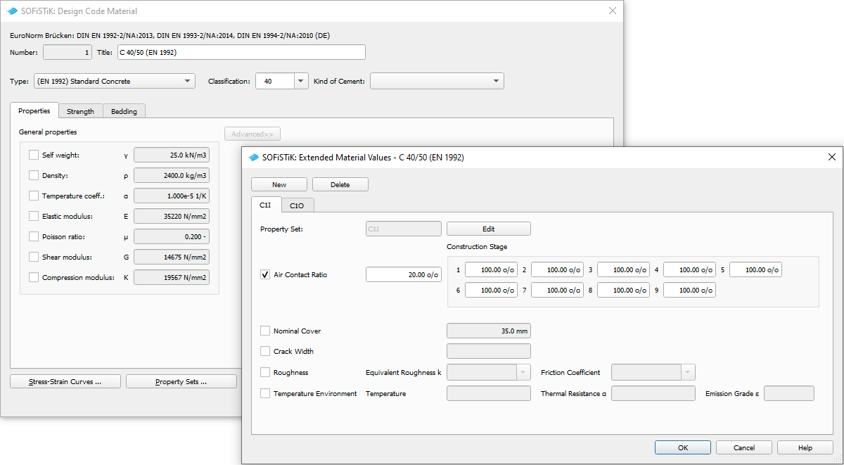
The information about the air contact ratio has to be defined at the corresponding concrete material. There is a special input record MEXT in the program AQUA or the subdialog ‘Property Sets’ for material in the SSD.
Material Definition with program AQUA#
With the record MEXT it is possible to define additional material information which is necessary for the cross section definition, e.g. information about the air contact ratio of concrete or temperature enviroments for a later fire design.
Here air contact ratio should be defined for concrete materials with the record MEXT. A separate record MEXT has to be input for each cross-sectional edge that provides different air contact ratios. The name given at item EXP is used later in the cross section definition for a polygon with the corresponding material number of the concrete. The first factor at item VAL is the air contact ratio of an edge in the end cross section. The factors which are input at VAL1 - VAL10 are the air contact ratios for cross-sectional edge in the construction stages.
The air contact ratio can be a factor (0 - 1) or a value in [%] (0 - 100 %).
CONC 1    C '30'  TITL "=C 30/37 (EN 1992) CS1"
  MEXT 1 EXP 'C1O' TYPE  AIR VAL 1 1            ! or VAL 100[%]  VAL1 100[%]
  MEXT 1 EXP 'C1I' TYPE  AIR VAL 0 1

STEE 2    B '500B'  TITL "=B 500 B (EN 1992) CS1"

CONC 3    C '30'  TITL "=C 30/37 (EN 1992) CS2"
  MEXT 3 EXP 'C2O' TYPE  AIR VAL 1 1
  MEXT 3 EXP 'C2I' TYPE  AIR VAL 0 1

STEE 4    B '500B'  TITL "=B 500 B (EN 1992) CS2"
Material Definition in the SSD#
The information about the air contact ratios can be input in the subdialog ‘Property Sets’ of the material dialog for concrete.
Cross Section Definition with AQUA#
File: solid-section-with-cs.dat
A T-beam section with two construction stage should be defined:
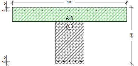
The polygon of the web is in the construction stage 10 and the polygon of the flange in construction stage 20.
Section 1 using the default settings
SECT 1 MNO 1 MRF 2 FSYM NONE BTYP BEAM TITL "t-beam with CS"
LAY 1 TYPE MIN MRF 2
LAY 2 TYPE MIN MRF 4
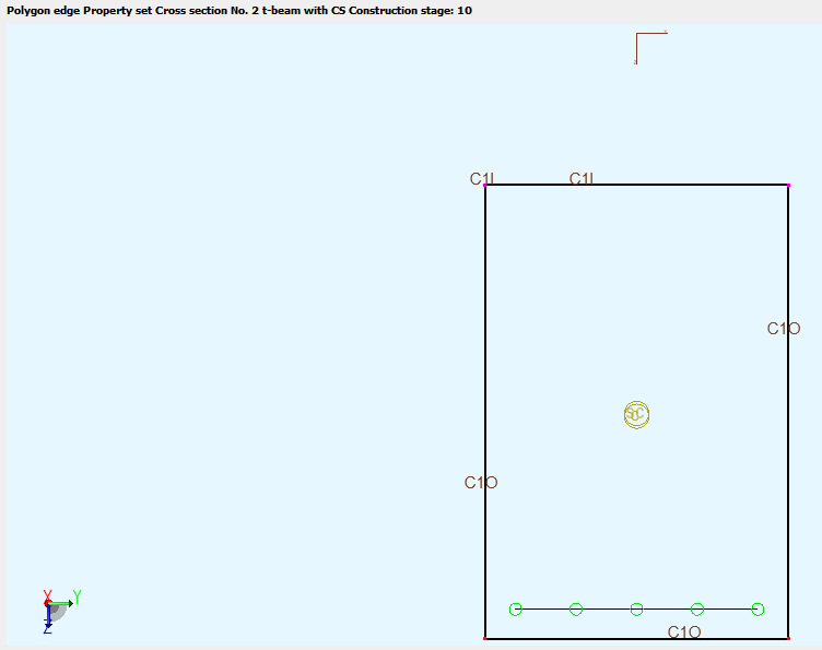
CS 10 TITL "CS 10"
POLY TYPE O MNO 1
VERT '0100' Y -250 Z 250
VERT '0101' Y 250 Z 250
VERT '0102' Y 250 Z 1000
VERT '0103' Y -250 Z 1000
LRF '0300' YB -200 ZB 950 YE 200 ZE 950 AS 1[-] LAY M1 TORS PASS D 20 A 5[-] DIST FULL
CS 20 TITL "CS 20"
POLY TYPE O MNO 3
VERT '0200' Y -1000 Z 0
VERT '0201' Y 1000 Z 0
VERT '0202' Y 1000 Z 250
VERT '0203' Y -1000 Z 250
LRF '0500' YB -950 ZB 50 YE 950 ZE 50 AS 5.24[cm2/m] LAY M2 TORS PASS D 10 A 150 DIST FULL
CUT 'CUT' YB -400. ZB 'S' YE 400. MNO 1 MRF 2 LAY 1 TYPE WEB INCL 90
Here the default settings of record VERT item EXP are used automatically with 1 for ventilated or 0 for not ventilated.
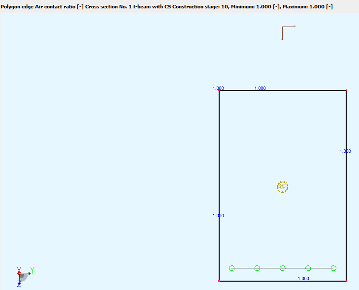
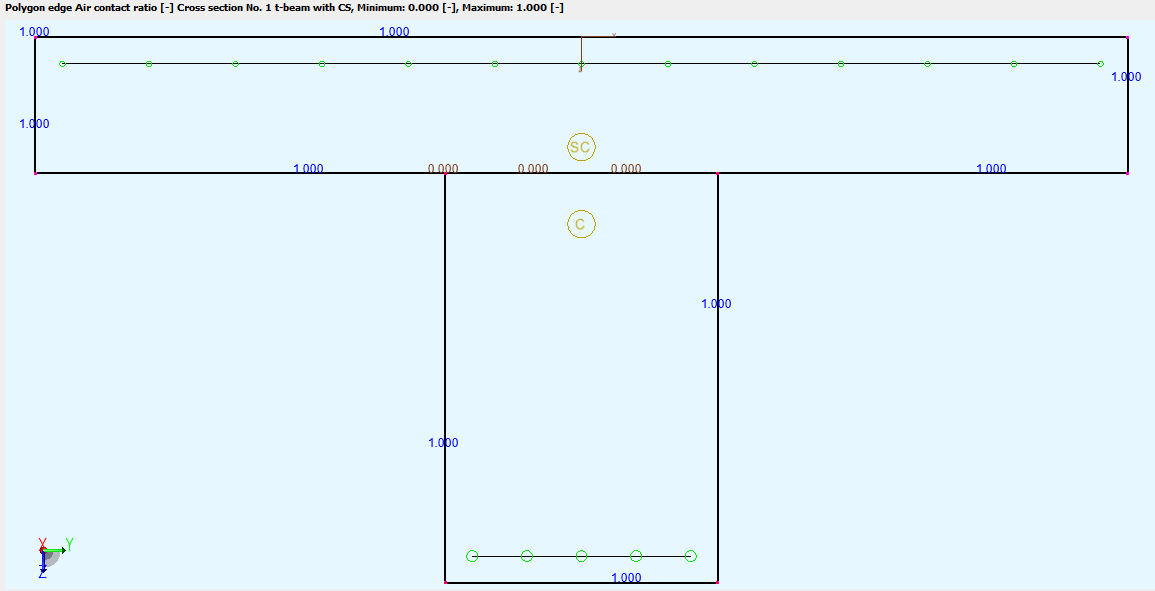
The result can be checked easily with the RESULT VIEWER:
section 1 construction stage 10 - web only
section 1 construction stage 20 = final stage
In the printout table Additional design data the calculated values of the effective depth deff are printed - section 1 construction stage 20 = final stage:
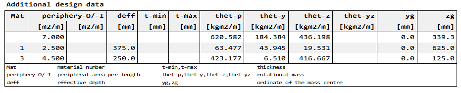
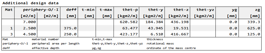
for the web with concrete no. 1:

for the flange with concrete no. 3:

Section 2 using explicit definition of the air contact ratio
The definition of the material values are shown above in the chapter ‘Material Definition with program AQUA’. For each concrete two classes (property sets) with air contact ratios are input:
concrete 1 with ‘C1O’ and concrete 3 with ‘C2O’ for the cross section edge which are ventilated in all cases
concrete 1 with ‘C1I’ for the web polygon - edge which is ventilated in construction stage 10 and not ventilated in construction stage 20
concrete 3 with ‘C2I’ for the flange polygon - edge which is not ventilated in the construction stage 20
Note
The name of the relevant class has to be input at the first polygonal point of the edge. E.g. with VERT ‘0100’ Y -250 Z 250 EXP ‘C1I’ the class C1I is valid for the edge from point 0100 till 0101.
SECT 2 MNO 1 MRF 2 FSYM NONE BTYP BEAM TITL "t-beam with CS"
LAY 1 TYPE MIN MRF 2
LAY 2 TYPE MIN MRF 4
CS 10 TITL "CS 10"
POLY TYPE O MNO 1
VERT '0100' Y -250 Z 250 EXP 'C1I'
VERT '0101' Y 250 Z 250 EXP 'C1O'
VERT '0102' Y 250 Z 1000 EXP 'C1O'
VERT '0103' Y -250 Z 1000 EXP 'C1O'
LRF '0300' YB -200 ZB 950 YE 200 ZE 950 AS 1[-] LAY M1 TORS PASS D 20 A 5[-] DIST FULL
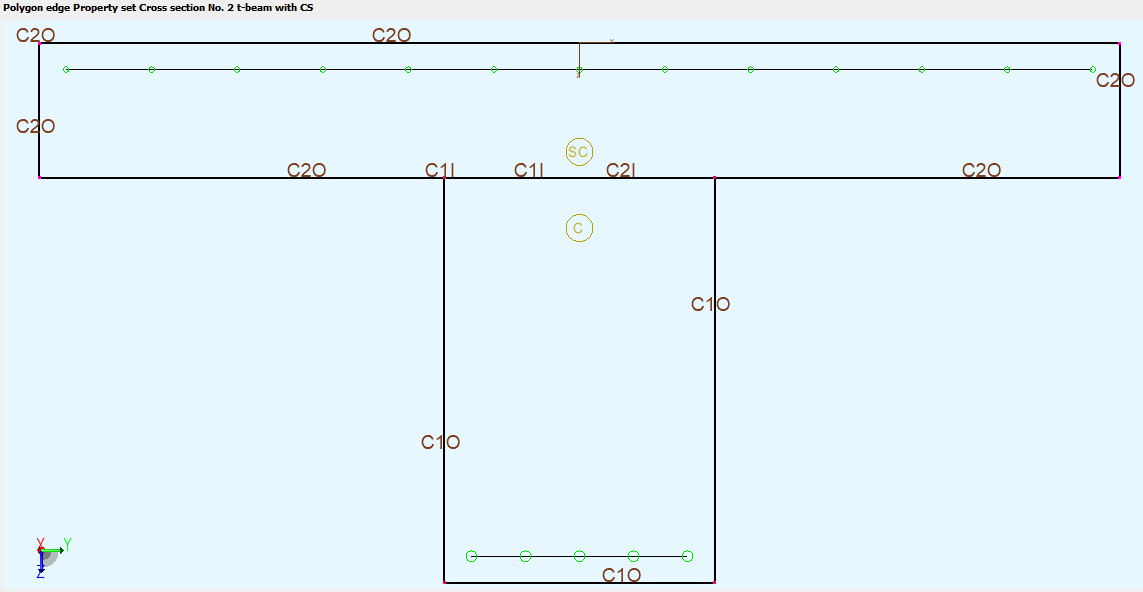
CS 20 TITL "CS 20"
POLY TYPE O MNO 3
VERT '0200' Y -1000 Z 0 EXP 'C2O'
VERT '0201' Y 1000 Z 0 EXP 'C2O'
VERT '0202' Y 1000 Z 250 EXP 'C2O'
VERT '0205' Y 250 Z 250 EXP 'C2I'
VERT '0204' Y -250 Z 250 EXP 'C2O'
VERT '0203' Y -1000 Z 250 EXP 'C2O'
LRF '0500' YB -950 ZB 50 YE 950 ZE 50 AS 5.24[cm2/m] LAY M2 TORS PASS D 10 A 150 DIST FULL
CUT 'CUT' YB -400. ZB 'S' YE 400. MNO 1 MRF 2 LAY 1 TYPE WEB INCL 90
The result are shown in the RESULT VIEWER:
section 2 construction stage 10 - web only
section 2 construction stage 20 = final stage
In the printout table Additional design data the calculated values of the effective depth deff are printed - section 2 construction stage 20 = final stage:
Cross Section Definition with the Cross-Section-Editor#
File: box-girder.sofistik
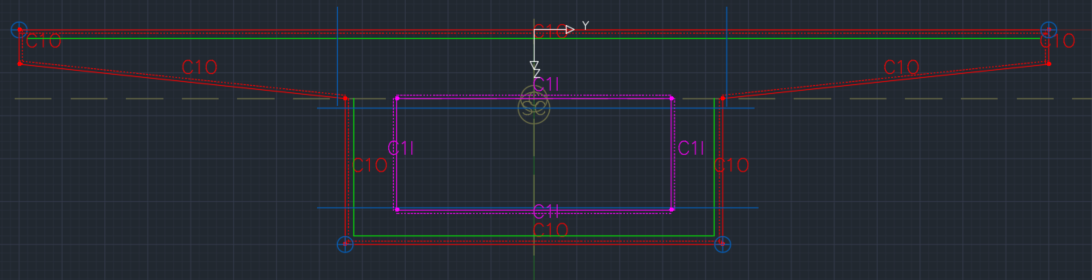
A box girder section should be defined:
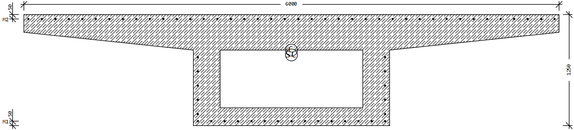
Section 1 using the default settings
Here no additional information about the air contact ratio is necessary. For boundary polygon the air contact ratio is used automatically with the factor 1 and the opening polygon with the factor 0.
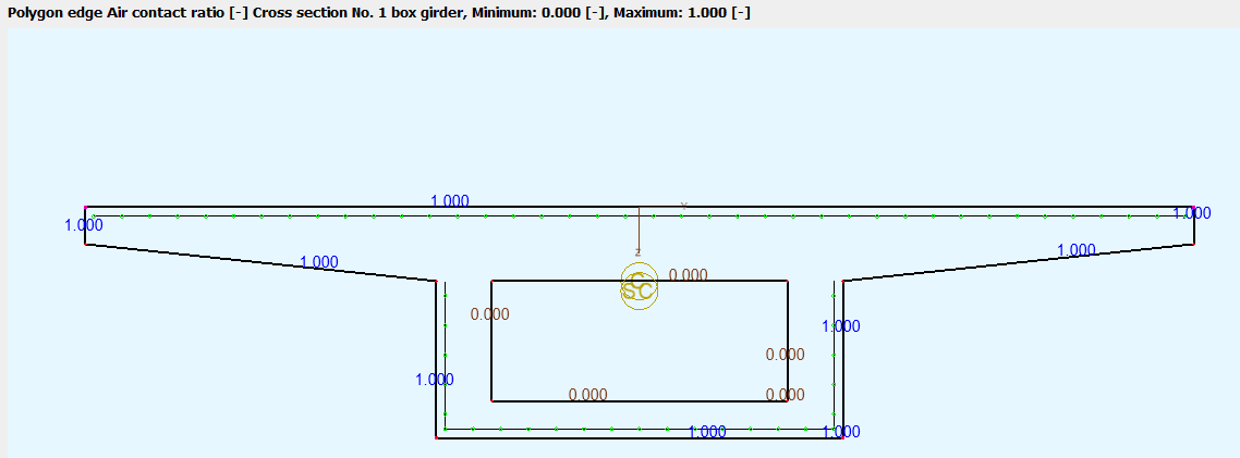
Section 2 using explicit definition of the air contact ratio
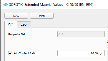
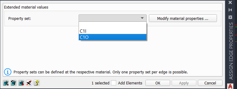
As above described the air contact ratio is defined in the subdialog ‘Property Sets’ of the material dialog for concrete. For the outer boundary the property set C1O is generated with 100[%] for ventilated. The property set C1I for the inner opening is defined here with an air contact ratio of 20[%]. Hollow box girders of bridges have maintenance openings so that they are partially ventilated.
After generating the geometry of the cross section 2 in the Cross Section Editor it is necessary to assign these property sets to the polygon edges with the command ‘Modifies the properties of boundary/opening edge’
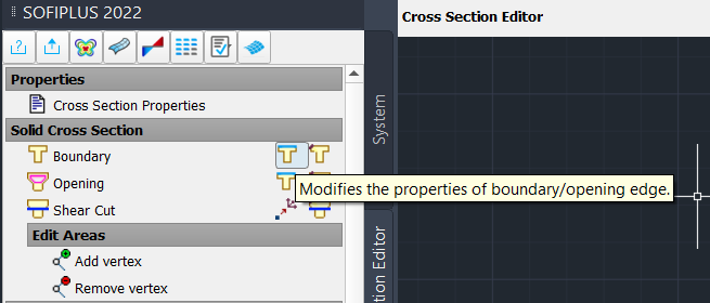
With a click on the icon polygon edges should be select. After this selection a dialog is opened where the property sets which are defined for the relevant concrete material of the polygon can be selected:
The associated property sets can be vizualized in the Cross Section Editor with the SOFiPLUS command Visualization in tab Tools.
Remarks#
If you need a detailed information about the definition of cross sections, contact us please with an email to support@sofistik.com.