Superposition of the Permanent Action G and Consideration of their Load Cases - Difference between PERM and PERC#
Introduction#
This document provides some explanations for the use of the permanent action G and the consideration of their load cases.
Theoretical Background#
EN 1990 and its National Annexes#
The design code EN 1990 allows all loads of a permanent action to be considered together if the scatter is small. If the scatter is larger, the individual load cases are to be considered separately as unfavourable or favourable.
Example#
Principle Workflow of the Example#
Generate the system inclusive the design code, materials, cross sections
Generate the actions with the task ‘Action Manager’ or with the program SOFiLOAD
Generate loads with the program SOFiLOAD
Run linear analysis
Generate action combinations in program MAXIMA (or in SSD task ‘Combinations’)
Generate superpositions (or SSD task ‘Superpositioning’)
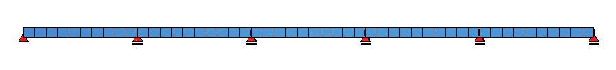
System Definitions#
A 5-span girder system with a rectangular cross section is present according to origin Eurocode as selected design code.
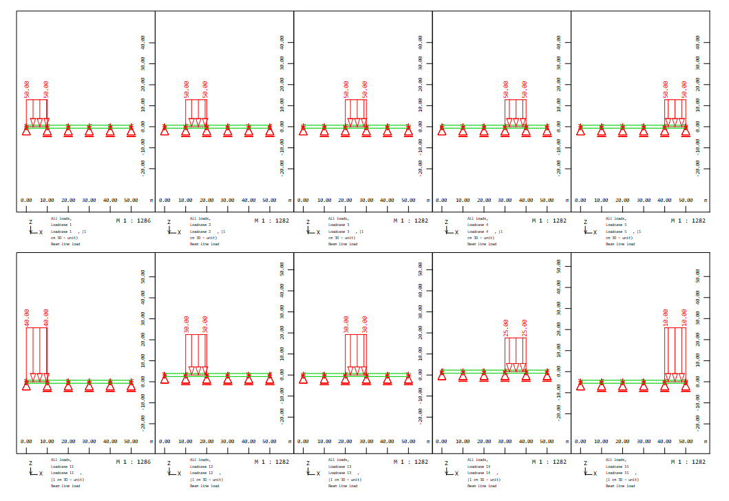
Actions and Load Definitions#
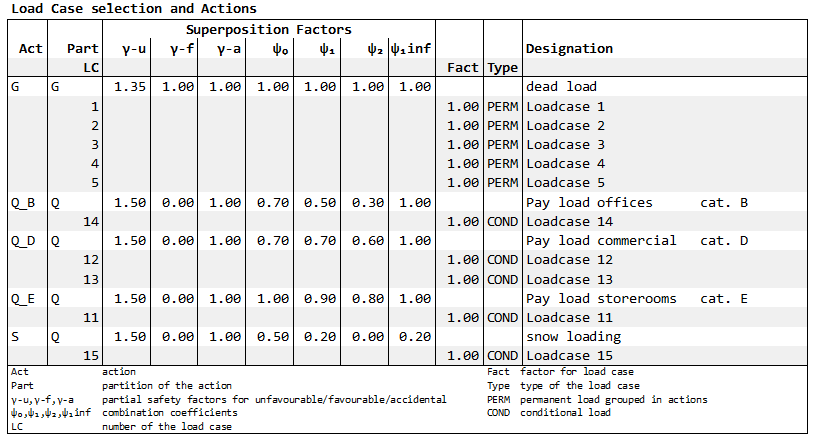
Following actions and corresponding load cases are defined:
Action G dead load with load cases 1 till 5 span-wise
Action Q category E Q_E pay load storage areas with load case 11
Action Q category D Q_D pay load shopping areas with load case 12,13
Action Q category B Q_B pay load offices areas with load case 14
Action S snow with load case 15
+PROG SOFILOAD
HEAD Actions
ACT  'G'   GAMU 1.35 1 PSI0 1 1 1 1 PART 'G' SUP PERM TITL "dead load"
ACT  'S'   GAMU 1.50 0 PSI0 0.5 0.2 0   0.2 PART 'Q' SUP COND TITL "snow loading"
ACT  'Q_B' GAMU 1.50 0 PSI0 0.7 0.5 0.3 1   PART 'Q' SUP COND TITL "Pay load offices      cat. B"
ACT  'Q_D' GAMU 1.50 0 PSI0 0.7 0.7 0.6 1   PART 'Q' SUP COND TITL "Pay load commercial   cat. D"
ACT  'Q_E' GAMU 1.50 0 PSI0 1   0.9 0.8 1   PART 'Q' SUP COND TITL "Pay load storerooms   cat. E"
END
In SOFiSTiK the load cases of the permanent action dead load G are preset with PERM - permanent with unique factor: ACT ‘G’ … PART ‘G’ SUP PERM. The decision whether all load cases of a permanent action are taken into account as favourable or unfavourable is effected by determination of sums. It means that either the favourable or unfavourable factor is used for all load cases.
+PROG SOFILOAD
HEAD Loads
echo full no

LC   1 'G' 1        TITL "Loadcase 1"
LINE SLN 1  TYPE PG P1 50
LC   2 'G' 1        TITL "Loadcase 2"
LINE SLN 2  TYPE PG P1 50
LC   3 'G' 1        TITL "Loadcase 3"
LINE SLN 3  TYPE PG P1 50
LC   4 'G' 1        TITL "Loadcase 4"
LINE SLN 4  TYPE PG P1 50
LC   5 'G' 1        TITL "Loadcase 5"
LINE SLN 5  TYPE PG P1 50

LC   11 'Q_E' 1     TITL "Loadcase 11"
LINE SLN 1  TYPE PG P1 40
LC   12 'Q_D' 1     TITL "Loadcase 12"
LINE SLN 2  TYPE PG P1 30
LC   13 'Q_D' 1 TITL "Loadcase 13"
LINE SLN 3  TYPE PG P1 30
LC   14 'Q_B' 1 TITL "Loadcase 14"
LINE SLN 4  TYPE PG P1 25
LC   15 'S' 1 TITL "Loadcase 15"
LINE SLN 5  TYPE PG P1 10
END
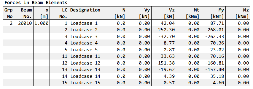
Linear Analysis and Resulting Bending Moments My#
After calculating the individual load cases, the following moment curves result for My:
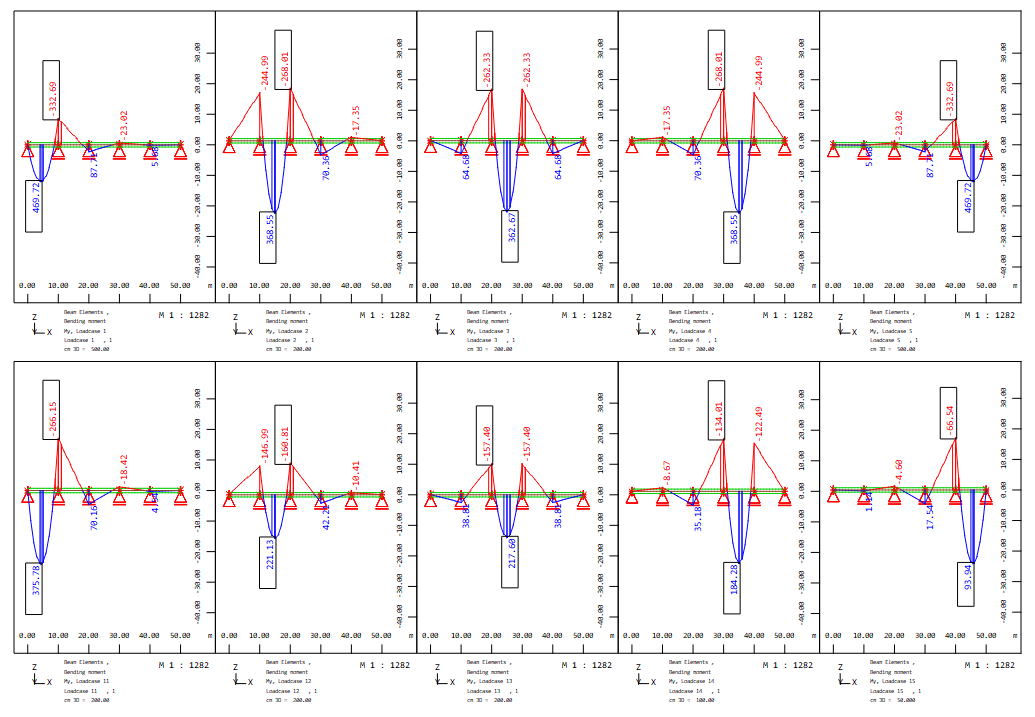
Furthermore, the bending moments at the 3rd support at node 3 should be considered as a superimposed variable.

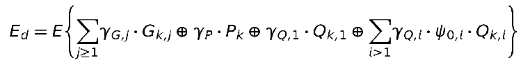
Action Combinations and Superpositions#
The used action combination is the fundamental combination for the ultimate limit state according to equation 6.10 of the EN 1990:
First variant
In the first variant the default setting of the action G - SUPP PERM ist used. The MAXIMA input is:
+PROG MAXIMA
HEAD G - LC PERM
ECHO LOAD,FACT
COMB 1 EXTR DESI TYPE DESI BASE 2100
 ACT G
 ACT Q_E
 ACT Q_D
 ACT Q_B
 ACT S
SUPP 1 EXTR MAMI ETYP BEAM TYPE MY FROM 20010 X 1[-]      ! full output for hogging moment column 3 = end of beam no. 20010
END
In the output table ‘Load Case Selection and Actions’ the load cases of the action G are marked as PERM for permanent in the column Type.
According to the input, the full output is printed for the bending moment at the bar end no. 20010.
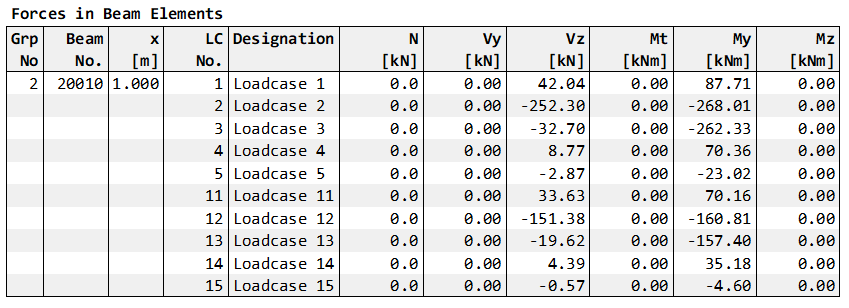
The prinout of the beam forces starts with the table of the initial load cases and their internal forces:
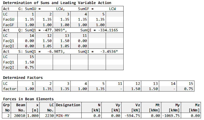
It follows the tables for the sum calculation, the determined factors and the superposition result. As an example, the results for min My are shown here:
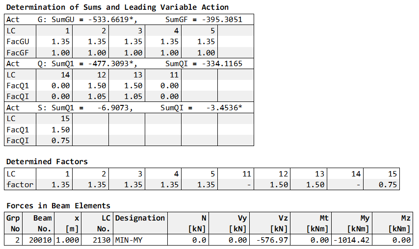
According to the determined sums for the load cases 1 - 5, the load cases for the dead loads have an unfavourable effect. Therefore, the factor 1.35 is given for all load cases and thus the minimum moment My is determined.
Second variant
For the second variant, the MAXIMA input for the analog combination 2 is changed. The type for the load cases dead load 1 - 5 is set to PERC. It is also possible to change this type at the action G value SUP PERC both in MAXIMA or also in SOFiLOAD (or Loadcase Manager).
Note
A modification of the action definitions in record ACT in program MAXIMA only affects the current action combination. However, a modification in record ACT in SOFiLOAD (or Loadcase Manager) is saved in the database and is valid for all action combinations.
The MAXIMA input is:
+PROG MAXIMA
HEAD G - LC PERC
ECHO LOAD,FACT
COMB 2 EXTR DESI TYPE DESI BASE 2200
 ACT G !SUP PERC                                           ! modification only for current combination
    LC (1 5 1) TYPE PERC                                   ! or definition for perc in record LC
 ACT Q_E
 ACT Q_D
 ACT Q_B
 act S
SUPP 2 EXTR MAMI ETYP BEAM TYPE MY FROM 20010 X 1[-]      ! full output for hogging moment column 3 = end of beam no. 20010
END
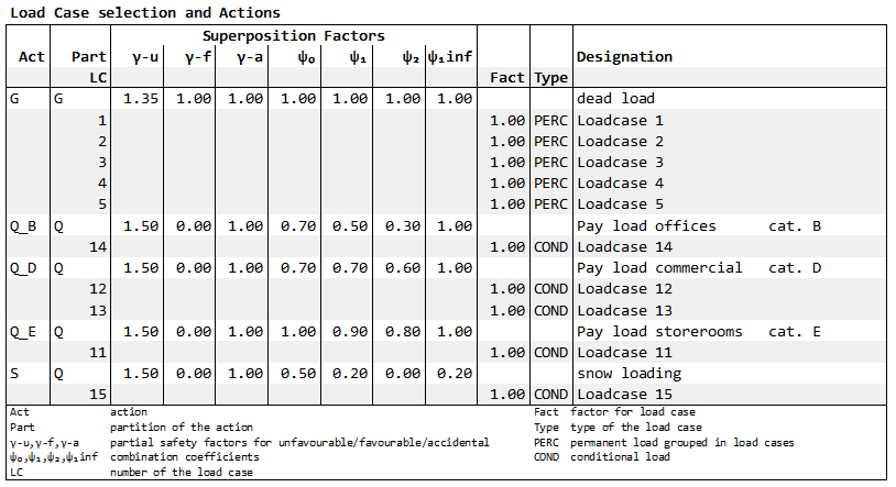
In the output table ‘Load Case Selection and Actions’ the load cases of the action G are marked as PERC for loadcase-wise in the column Type.
In the table of the sums the sums of the action G are marked with LCW for loadcase-wise determination. The determined factors for the load cases 1 - 5 are different. With reference to the superposition value My, the factors are as follows:
for load cases 1 and 4 with a positiv moment My - the favourable safety factor 1.0
for load cases 2,3,5 with a negativ moment My - the unfavourable safety factor 1.35
Remarks#
The different definitions for the consideration of the load cases PERM or PERC of permanent actions lead to different superposition results. Which option is used depends on the specific task and is at the discretion of the engineer.
If you need a special solution for the topic of the combinations and superpositions of your project, contact us please with an email to support@sofistik.com.