Superposition of the Action with Categories using Alternative Load Groups - Difference between ALEX, EXCL and EXEX#
Introduction#
This document provides some explanations for the use of the permanent load groups and alternativ load groups. The definition at the actions controls, how the initial load cases are considered in an action or within the categories of an action. This is usually not part of the design codes but is the decision of the engineer.
Example#
Principle Workflow of the Example#
Generate the system inclusive the design code, materials, cross sections
Generate the actions with the task ‘Action Manager’ or with the program SOFiLOAD
Generate loads with the program SOFiLOAD
Run linear analysis
Generate action combinations in program MAXIMA (or in SSD task ‘Combinations’)
Generate superpositions (or SSD task ‘Superpositioning’)
System Definitions#
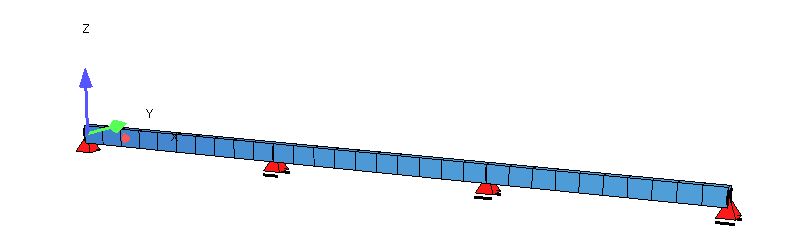
A 3-span girder system with a rectangular cross section is present according to origin Eurocode as selected design code.
Actions and Load Definitions#
Following actions are defined:
Action G dead load
Action X categories 1 - 3 as permanent action (PART G) with consideration of the load cases SUP ALEX - permanent but exclusive within action
Action Z categories 1 - 3 as permanent action (PART Q) with consideration of the load cases SUP EXCL - exclusive within category
+PROG SOFILOAD
HEAD Actions
ACT  'G'   GAMU 1.35 1 PSI0 1 1 1 1 PART 'G' SUP PERM TITL "dead load"

! action X with categies as permanent action PART G with SUP ALEX
ACT 'X_1'  GAMU 1.20 1 PSI0 1 1 1 1 PART 'G' SUP ALEX TITL "X cat. 1"
ACT 'X_2'  GAMU 1.20 1 PSI0 1 1 1 1 PART 'G' SUP ALEX TITL "X cat. 2"
ACT 'X_3'  GAMU 1.20 1 PSI0 1 1 1 1 PART 'G' SUP ALEX TITL "X cat. 3"

! action Z with categies as variable action PART Q with SUP EXCL
ACT 'Z_1'  GAMU 1.50 0 PSI0 0.7 0.5 0.3 1 PART 'Q' SUP EXCL TITL "Z cat. 1"
ACT 'Z_2'  GAMU 1.50 0 PSI0 0.9 0.7 0.5 1 PART 'Q' SUP EXCL TITL "Z cat. 2"
ACT 'Z_3'  GAMU 1.50 0 PSI0 0.8 0.6 0.4 1 PART 'Q' SUP EXCL TITL "Z cat. 3"
END
Note
Already the definition of the item SUP has a decisive influence on the superposition result. The specification can be temporarily changed in MAXIMA for individual action combinations (except for explicit defined combination with action groups).
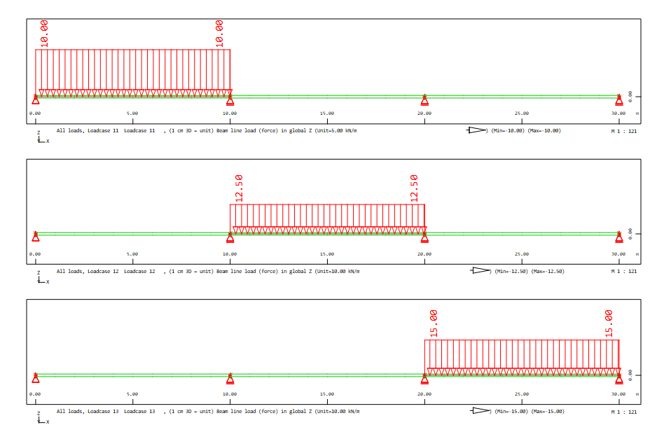
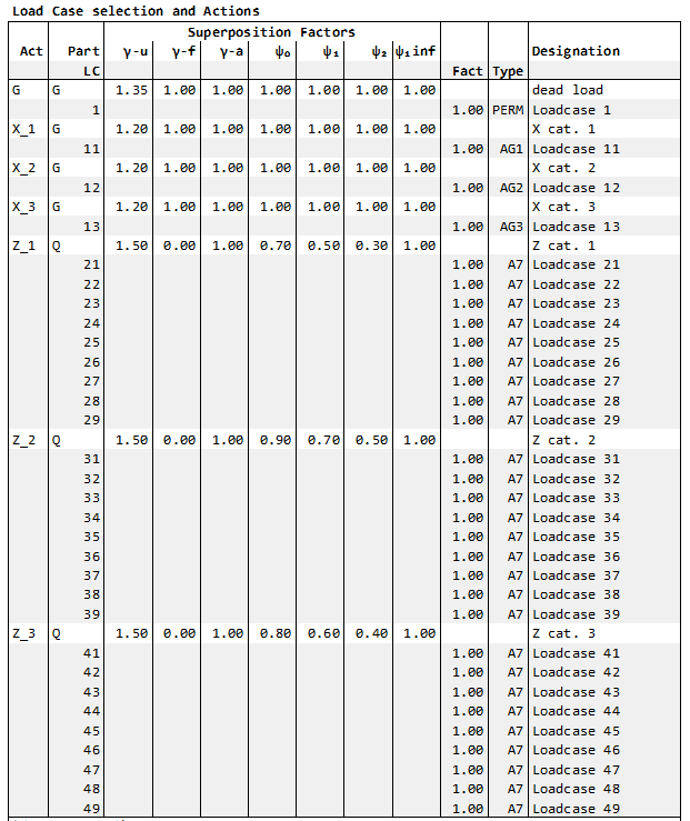
Corresponding load cases:
Action / Category |
LC number |
Load |
|---|---|---|
X_1 |
11 |
line load in span 1 |
X_2 |
12 |
line load in span 2 |
X_3 |
13 |
line load in span 3 |
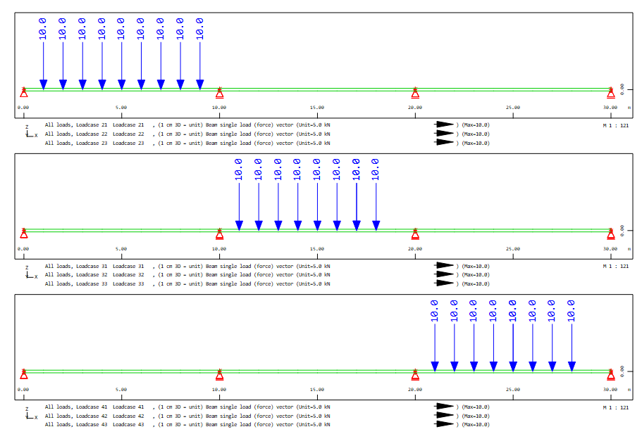
Z_1 |
21 - 29 |
point loads as running imposed loads in span 1 |
Z_2 |
31 - 39 |
point loads as running imposed loads in span 2 |
Z_3 |
41 - 49 |
point loads as running imposed loads in span 3 |
Linear Analysis and Resulting Bending Moments My#
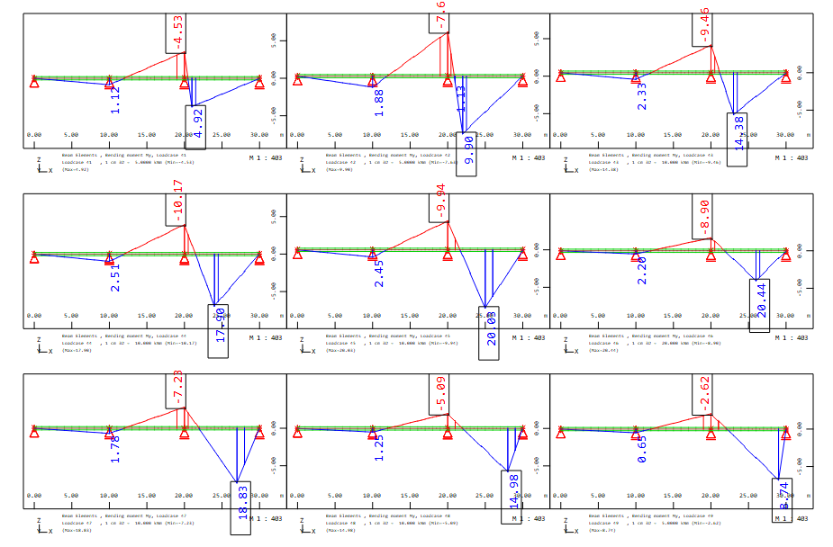
After the linear analysis with program ASE following bending moment My are availalbe:
for load cases 11 - 13 action X_1, X_2 and X_3
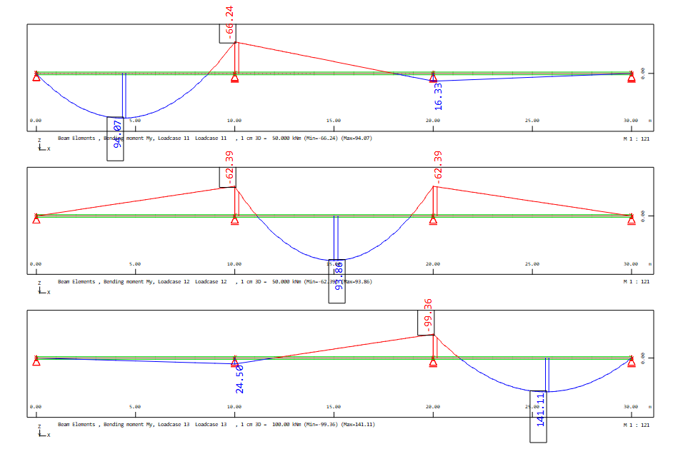
for load cases 21 - 29 action Z_1
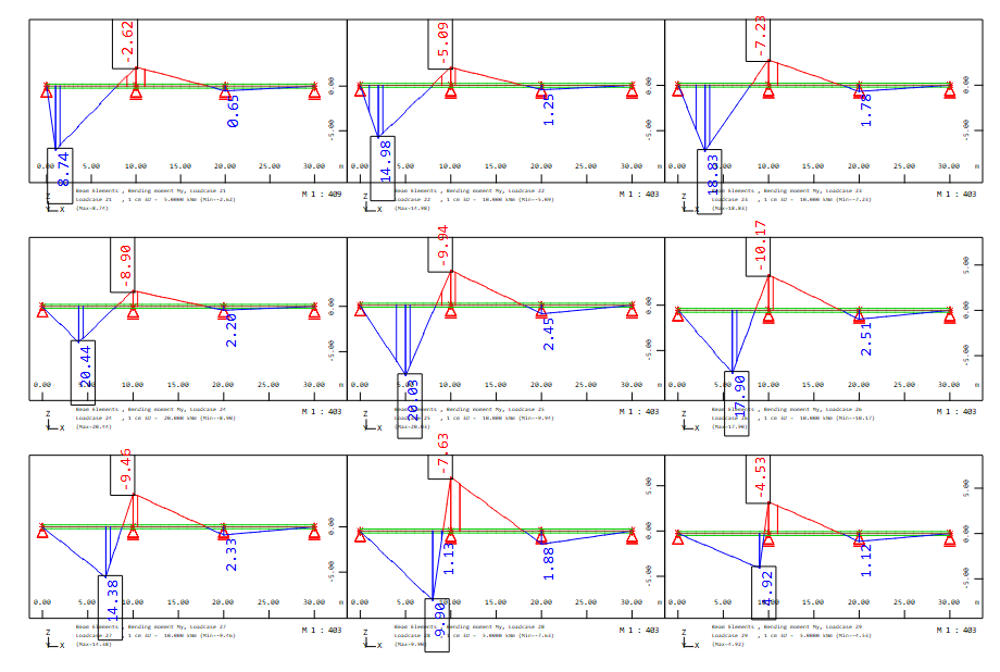
for load cases 31 - 39 action Z_2
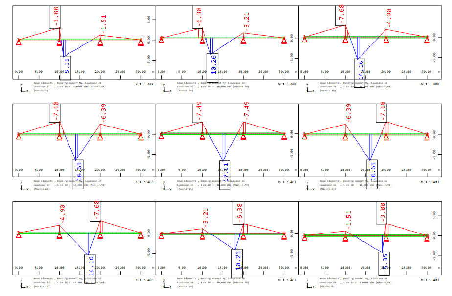
for load cases 41 - 49 action Z_3
Action Combinations and Superpositions#
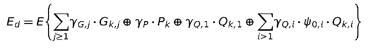
The used action combination is the fundamental combination for the ultimate limit state according to equation 6.10 of the EN 1990:
Furthermore, the bending moments at the 2rd support between 2nd and 3rd span should be considered as a superimposed variable.
Combination 1 for Ultimate Limit State equation 6.10 EN 1990 with definitions of the actions and load cases from program SOFiLOAD
Here the action with their corresponding load cases are used as defined in program SOFiLOAD:
+PROG MAXIMA
HEAD Combination 1
ECHO LOAD,FACT
COMB 1 EXTR desi TYPE desi BASE 2100
ACT G
ACT X_1
ACT X_2
ACT X_3
ACT Z_1
ACT Z_2
ACT Z_3
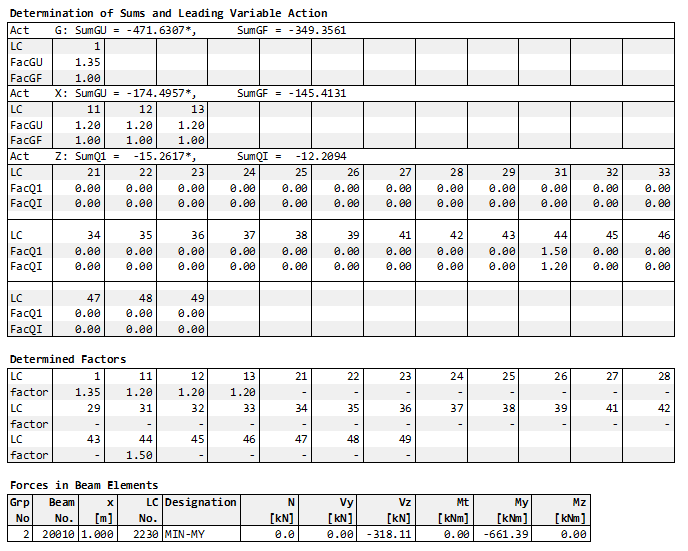
SUPP 1 EXTR mami ETYP beam TYPE MY FROM 20010 X 1[-] ! full output for hogging moment column 3 = end of beam no. 20010
END
The MAXIMA output table ‘Load Case Selection and Actions’ column Type shows how the load cases are assigned to the alternative load groups:
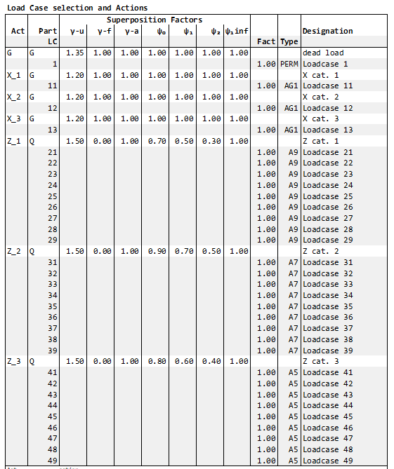
The load cases 11,12,13 of the permanent action X with their categories 1 - 3 are assigned to the permanent alternativ group AG1 as defined for the action with SUP ALEX. For the superposition results, this means that only one load case is taken into account.
For the variable action Z the load cases of the individual categories are assigned to different load groups A9, A7 and A5 as defined for the action and their categories with SUP EXCL. For the superposition results, this means that one or no load case is taken into account per category because they are variable loads. For the entire action Z, one, two, three or no load cases can be included in the result.
For the minimum bending moment My at the third column between span 2 and 3 (beam no. 20010 beam end) the superposition result looks as follows:
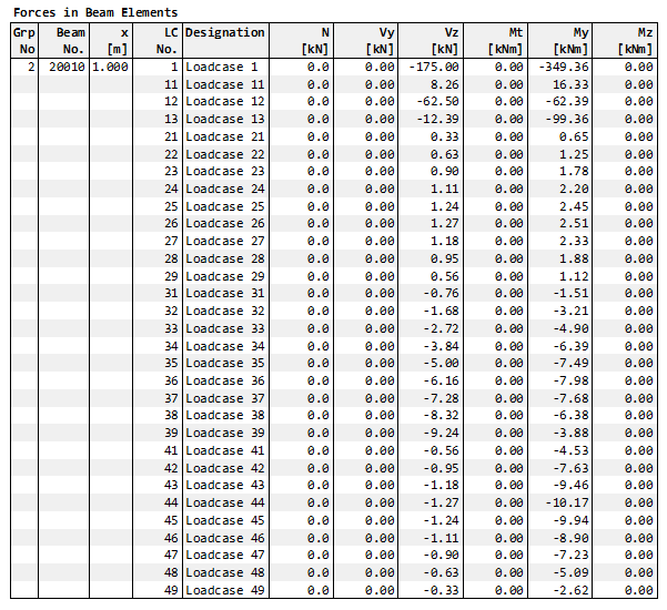
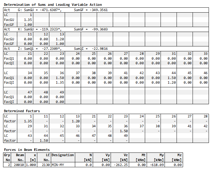
For the permanent action Z, only one load case is considered due to the definition in one permanent alternative load group. The most unfavourable contribution is provided by load case 13 with the factor GAMU = 1.2
The load cases 21 - 29 of the variable action Z category 1 only have a favourable effect and are not taken into account. On the other hand, all load cases 31 - 39 of category 2 and 41 - 49 of category 3 have an unfavourable influence. Thus, one load case of category 2 and one of category 3 are included in the superposition:
most unfavourable load case 36 of Z_2 with factor GAMU = 1.5
most unfavourable load case 44 of Z_3 with factor GAMU = 1.5
Combination 2 for Ultimate Limit State equation 6.10 EN 1990 with modifications of consideration for the load cases
In combination 2 the load cases of the permanent action X with categories 1 - 3 are assigned to different permanent load groups AG1 - AG3.
The categories of the action Z are modified in order to assign all load cases to one alternative load group. This can be done with two input variants:
Modification of the categories in records ACT with SUP EXEX - exclusive within action
Assignment of all load cases to the alternative load group A7 in records LC with TYPE A7
All load cases of the variable action Z with their categories receive now the one alternative load group A7. It means only one load case of 21 - 49 ist considered and only if it acts unfavourably. Thus, it is possible that none of these load cases are included in the superposition.
+PROG MAXIMA
HEAD Combination 2
ECHO LOAD,FACT
COMB 2 EXTR desi TYPE desi BASE 2200
 ACT G
 ACT X_1
   LC 11  TYPE AG1              ! different permanent load groups for X_1, X_2 and X_3
 ACT X_2
   LC 12  TYPE AG2
 ACT X_3
   LC 13  TYPE AG3
 ACT Z_1  SUP EXEX              ! modifiaction SUP EXEX alternativ within action  or defintion at LC
   ! LC (21 29 1) TYPE A7       ! same variable load group for Z_1, Z_2 and Z_3
 ACT Z_2  SUP EXEX
   ! LC (31 39 1) TYPE A7
 ACT Z_3  SUP EXEX
   ! LC (41 49 1) TYPE A7
SUPP 2 EXTR mami ETYP beam TYPE MY FROM 20010 X 1[-]      ! full output for hogging moment column 3 = end of beam no. 20010
END
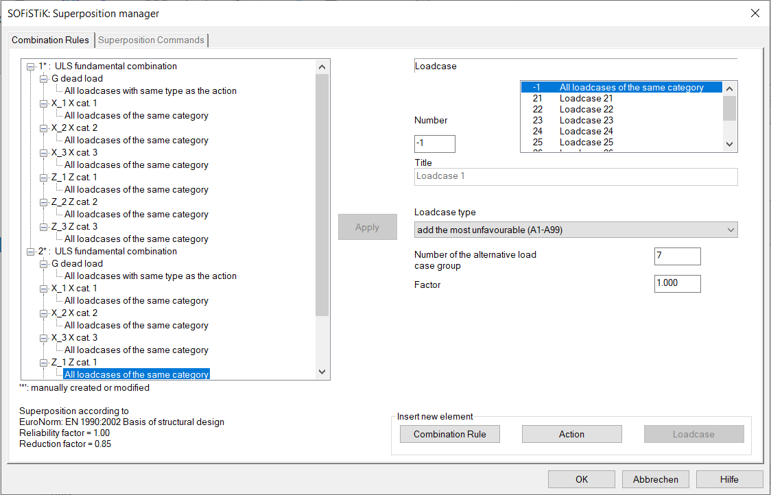
In the SSD task ‘Combination Rules’ only the 2nd variant with defintion at the load cases with alternative group A7 is possible:
The MAXIMA output table ‘Load Case Selection and Actions’ column Type shows how the load cases are assigned to the alternative load groups:
For the minimum bending moment My at the third column between span 2 and 3 (beam no. 20010 beam end) the superposition result looks as follows:
For the permanent action Z, the sum of the three load cases 11 - 13 is used to determine whether they have a favourable or unfavourable effect. Here they have an unfavourable effect. Due to three permanent alternative load groups AG1 - AG3, all three load cases are considered with the factor GAMU = 1.2.
The load cases 21 - 29 of the variable action Z category 1 only have a favourable effect and are not taken into account. On the other hand, all load cases 31 - 39 of category 2 and 41 - 49 of category 3 have an unfavourable influence. Since all load cases belong to only one alternative load group A7, only the most unfavourable load case 44 with the factor GAMU = 1.5 is used.
Remarks#
The different definitions for the consideration of the load cases in permanent or alternative load groups lead to different superposition results. Which option is used depends on the specific task and is at the discretion of the engineer.
If you need a special solution for the topic of the combinations and superpositions of your project, contact us please with an email to support@sofistik.com.