General Explanations for the Use of MAXIMA - Action Combinations in order to get Design Forces or Load Case Combinations#
Introduction#
This document provides some explanations for the use of the program MAXIMA.
Theoretical Background#
In the several design codes action combinations are given for the superposition of different loads (e.g. dead load, variable loads, accidental and seismic loads) in order to determine the design values for ultimate and serviceability limit states.
For the European countries the several action combinations are defined in the EN 1990 and their corresponding National Annexes, for Switzerland in the SIA 260 and for Russia in SP 20.13330. These design codes superimpose the actions according to the partial factor method.
EN 1990 and its National Annexes#
For the fundamental combination for the ultimate limit state the EN 1990 gives several possibilities:
Use of the equation 6.10
Or use of the equations 6.10a and 6.10b.
Additionally, the equations 6.10a and 6.10b are different in the several National Annexes due to the defined use of the reduction factor Xsi and the reliability (consequences class) factor Kfi.
For the accidental combination, the EN 1990 gives also two possibilities dependent on the corresponding accidental action (impact or fire) and for the design task consequently.
SIA 260#
The Swiss code defines a fundamental action combination for the ultimate limit state, however, only similar to equation 6.10 of the EN 1990.
SP 20.13330#
The Russian definition is very complex for the general case. A detailed description with an example file can be found in the tutorial: Superposition according to Russian SP 20.13330.2016: Loads and Actions https://www.sofistik.de/documentation/2020/en/tutorials/superpositions/russian_sp-20-13330-2016/superposition_sp-20-13330-2016.html
Other Codes#
Other design codes, e.g. ACI 318 (American Concrete Institute) or BS 8110 (British Standard), define several combinations with different fixed defined unfavourable factors for the used actions.
All codes have in common that there is a corresponding general specification of action combinations. The task of the engineer is now to apply these general specifications for his project and to determine the appropriate internal forces or load case combinations for the corresponding design task.
Basics of the Program MAXIMA#
Using the program MAXIMA, SOFiSTiK offers various options for determining automatically or manually the design internal forces or load case combinations.
Requirements#
The actions have to be defined with the program SOFiLOAD record ACT or with the SSD task ‘Action Manager’. For each design code SOFiSTiK offers default actions with all necessary information which can be select in SOFiLOAD only with their designation or in the task ‘Action Manager’. Of course, user-specific actions can also be defined. There have to be initial load cases with loads and their assignment to an action. These load cases should be calculated and results have to be available in the database.
The procedure in the program MAXIMA can be divided into two parts:
1st Part: Definition of the Action Combinations#
This part depends on the design code which was defined by the user in the task ‘System Information’ or in program AQUA record NORM. Here the appropriate design code for the specific design task of the structural system should be defined. The preset actions and action combinations are then according to the associated code or definitions for the basics of structural design.
The preset actions combinations are only valid for the use of preset actions. In the case of manually defined actions, the action combinations have to be checked and adapted by the user.
Important
Please note, that default action combinations for the selected design code are only available for buildings and not for bridges. The SOFiSTiK workflow for the more complex action combinations for bridges is done with the program CSM - Construction Stage Manager or the CSM task in the SSD. This is not a part of this tutorial.
Necessary definitions:
Definition of the combination rule - MAXIMA record COMB
Assignment of the used actions - MAXIMA records ACT or ADD and ADA in dependence on the selected combination rule
Assignment of the initial load cases to the corresponding actions, if necessary (or automatically) - MAXIMA record LC in dependence on the selected combination rule
If the graphical input is used with the SSD, this corresponds to the SSD task ‘Define Combinations’.
Particularities of the combination rule definition:
The program MAXIMA includes some predefined combination rules according to the EN 1990 (MAXIMA manual chapter 2.2: Combinations according to EN 1990 and DIN 1055-100/DIN-FB). These combination rules can used with the input of the specific literal in record COMB item EXTR or in the SSD task ‘Define Combinations’ Button Combination Rule -> Insert EN combination rule.
Item EXTR literal |
Designation |
Corresponding formula in EN 1990 |
|---|---|---|
DESI |
ULS fundamental combination |
equation 6.10 EN 1990 |
ACCI |
ULS accidental combination |
equation 6.11 EN 1990 with leading variable action Psi1,1*Qk,1 |
EARQ |
ULS seismic combination |
equation 6.12 EN 1990 |
RARE |
SLS characteristic (rare) combination |
equation 6.14 EN 1990 |
FREQ |
SLS frequent combination |
equation 6.15 EN 1990 |
PERM |
SLS permanent combination |
equation 6.16 EN 1990 |
NONF |
SLS infrequent combination |
equation A.2.1 EN 1990 Appendix A2 road bridges |
Important
All other rules for action combinations have to be defined as explicit defined combination - record COMB item EXTR EXPL or in the SSD task ‘Define Combinations’ Button Combination Rule -> Insert explicit combination rule.
This is also valid for the accidental combination with leading variable action Psi2,1*Qk,1 according to equation 6.11 EN 1990.
2nd Part: Definition of the Superposition Values#
This part is independent on any design codes and the same in all cases. This defines what is to be superimposed and how (maximum and / or minimum value).
The program MAXIMA superimposes the results of the calculation of single load cases. These can be the following values:
Internal forces and moments
Support and boundary forces
Displacements and rotations
Bedding values
Spring values
Storey results for seismic design
For special cases it is also possible to define objective functions for the superpositions. Here preset objective functions can be selected or they can be defined manually as formula by the user. Preset objective functions are:
Normal and shear stresses in specific points of the cross sections for beams or design elements
Equivalent stress (Von Mises) for QUAD elements
Here the superposition is done according the objective function, however, only the corresponding internal forces are saved.
These possibilities correspond to the program MAXIMA record SUPP or the SSD task ‘Superpositioning’.
Internal Process in Program MAXIMA#
Please note that the program MAXIMA calculates for each single superposition values at all positions of the structure the leading variable action and the accompanying variable actions with their relevant load cases. This means that, depending on the system and the loads, there are many resulting load case combinations with the relevant result.
Important
In the database only the results of the superpositions are stored in order to use for the corresponding design task.
Resulting load case combinations are not stored in the database. It is possible to automatically determine load case combinations only for girder systems or columns in the SSD tasks ‘Combine Loads’ or ‘Combine Results’ with the Button ‘Automatic’. This automatic determination is done internally with the MAXIMA engine. The resulting load case combinations of the task ‘Combine Loads’ can be used for non-linear calculations of girder systems or columns. A detailed description of this internal process is available in the tutorial: Determination of Decisive Load Case Combinations with Superposition of Normal Stresses in Cross Section Points https://www.sofistik.de/documentation/2020/en/tutorials/superpositions/bb14-bockhold-vossen/superposition_bb14-bockhold-vossen.html
Possibilities for the Printout to Check the Results#
The preset printout information and tables are:
Number, title, equation of the action combination and type of the resulting load cases as necessary information for the design task
Tables of the combinations including the corresponding initial load cases
Table of the resulting load cases numbers and titles
There are also various output options for checking individual results on a random basis -> MAXIMA manual record ECHO or Tab Output in the SSD task ‘Superpositioning’
Hint
It is recommended to request the detailed printout only for individual values for specific elements (nodes, beam etc.). A full printout for everything may generate thousands of pages, needs a lot of time and is cancelled by MAXIMA from a certain size with a warning.
The following small examples show these possibilities for input definitions and printout.
Examples#
Principle Workflow of all Examples#
Generate the system inclusive the design code, materials, cross sections
Generate the actions with the task ‘Action Manager’ or with the program SOFiLOAD
Generate loads with the program SOFiLOAD
Run linear analysis
Generate action combinations in program MAXIMA (or in SSD task ‘Combinations’)
Generate superpositions (or SSD task ‘Superpositioning’)
Generate decisive load case combinations using SSD task ‘Combine Loads’ (or task ‘Combine Results’) with button ‘Automatic’
Basic Definitions of all Examples#
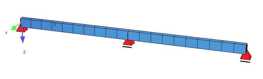
The following four examples have the same system (or in the case of the example US ACI318-14 similar system due to the units): a two-span girder
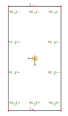
A simple rectangular concrete beam is defined as cross section. The picture shows the cross section with the reinforcement layers and the preset stress points Z+ and Z- which are used later for the superposition of the normal forces in beam sections.
The system is loaded with the dead load, an additional dead load for both spans, a variable load on the first span and a snow load on the second span:
Dead load G (or D for US ACI318-14) with load cases 1 and 2
Variable load for offices Q_B (or L for US ACI318-14) with load case 3
Snow load S with load case 4
The possibilities of MAXIMA are explained below using the four examples with following design codes:
DIN EN 199x-200x: National Annexes of the DIN EN 1992-1-1/NA, DIN EN1993-1-1/NA, DIN EN1994-1-1/NA for Germany including the information of the National Annex of the DIN EN 1990/NA with equation 6.10
SS EN 199x-200x: National Annexes (EKS 11:2019) of the SS EN 1992-1-1/NA, SS EN1993-1-1/NA, SS EN1994-1-1/NA for Sweden including the information of the National Annex of the SS EN 1990/NA with equation 6.10a and 6.10b
SIA 26x: Swiss Codes SIA 262, SIA 263, SIA 264 including the information of SIA 260
US ACI318-14: American Concrete Institute (2014)
Since the generation of the action combinations is extensive, only the possibilities and results for the action combinations of the ultimate limit state is explained here. As a default, the action combinations of the serviceability limit state are of course also available and included in the data files.
There are two data sets for each example: an DAT file with MAXIMA definitions and the same information as an SSD file with the graphical definitions.
First Example according to DIN EN199x-200x#
Files: din_en1992-2004_girder.dat and ssd2020-din_en1992-2004_girder.sofistik
After the definition of the material, the cross section and the system generation the actions and the loads are input.
Hint
For the preset actions it is only necessary to input the action name. All other information about the preset actions are generated automatically.
+PROG SOFILOAD
HEAD Actions
ECHO ACT
ACT  'G'   TITL "dead load"                        ! default action G
ACT  'Q_B' TITL "Pay load offices cat. B"          ! default action Q category B offices
ACT  'S'   TITL "snow loading"                     ! default action S
END

+PROG SOFILOAD
HEAD Loads
ECHO ACT FULL   ! table of the actions with associated load cases
LC   1 'G' 1 FACD 1 TITL "dead load"
LC   2 'G' 1 TITL "add dead load"
LINE SLN '1' WIDE 0 TYPE PG P1 15 0 0 0 P2 15 10 0 0
LINE SLN '2' WIDE 0 TYPE PG P1 20 10 0 0 P2 20 20 0 0
LC   3 'Q_B' 1 TITL "variable load"
LINE SLN '1' WIDE 0 TYPE PG P1 25 0 0 0 P2 25 10 0 0
LC   4 'S' 1 TITL "snow load"
LINE SLN '2' WIDE 0 TYPE PG P1 10 10 0 0 P2 10 20 0 0
END
The input of the actions in the SSD task ‘Action Manager’ is:
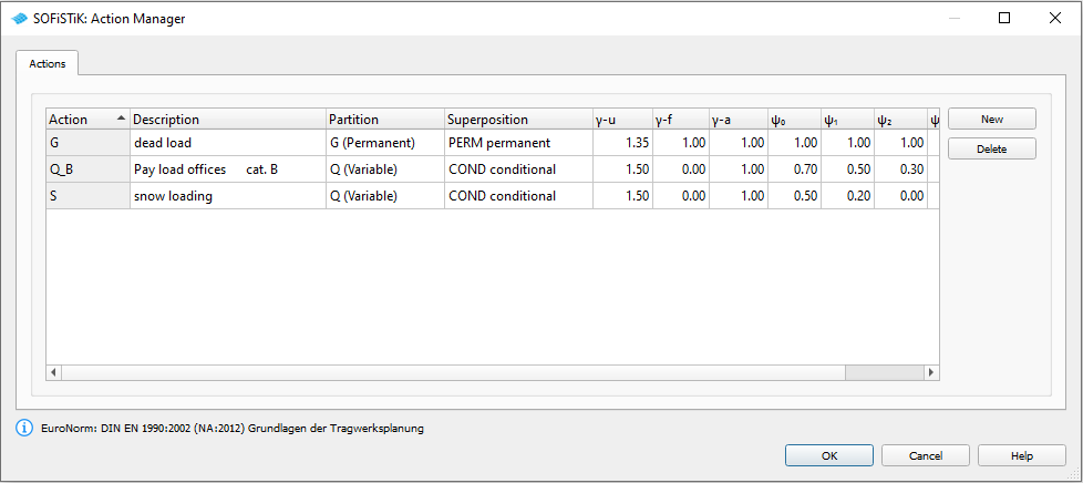
In connection with the input of the loads it is possible to set ECHO ACT FULL for the printout table of the used actions and the corresponding load cases:

After the calculation of the single load cases the superpositions are done in order to get the necessary design values (e.g. internal forces and moments, support reactions etc.).
In the first MAXIMA the preset action combinations and their preset superposition values are calculated. In order to get these defaults only the following simple MAXIMA should run:
+PROG MAXIMA
HEAD Preset action combinations
CTRL INIT 1                          ! does not delete the combinations in the 2nd run
ECHO TABS YES
END
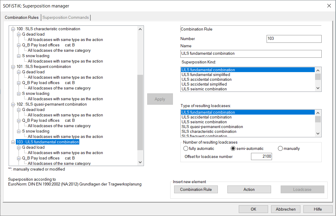
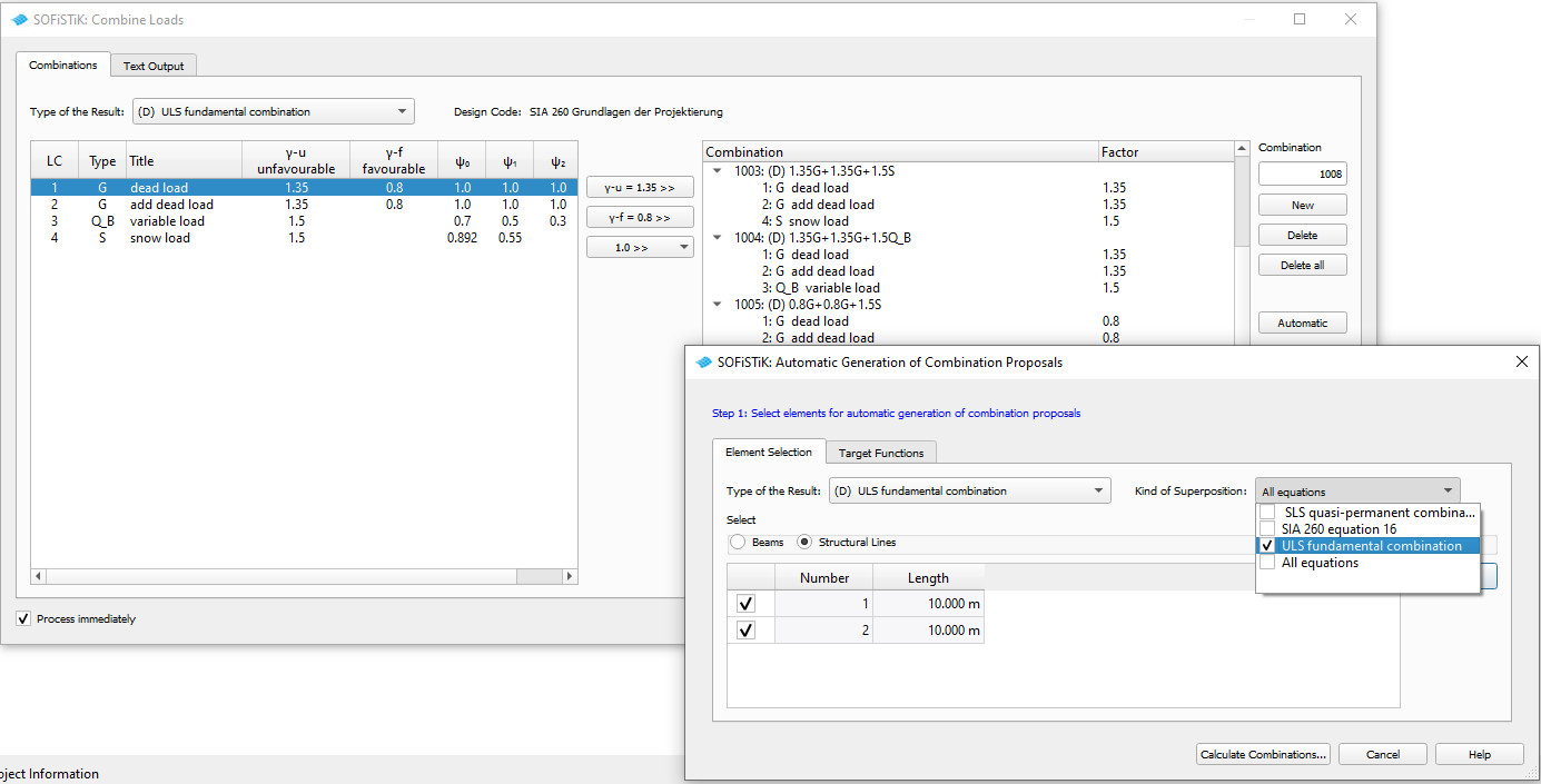
Or in the SSD the preset action combinations are shown in the task ‘Define Combinations’ and the superposition values are shown in the task ‘Superpositioning - preset superpositions’:
Please note, that all for a 3D system possible superposition values are preset. For this small system e.g. for the beam forces only Vz and My are interesting. In the SSD example only these values are set here manually.
Hint
If you want to get the complete MAXIMA (CADINP) input of the preset action combinations and superpositions, you can use the export from CDB to MAXIMA inside TEDDY or SSD (Button Database Tools -> Export to DAT).
The printout contains the general information about the action combinations and the table of the generated resulting load cases:
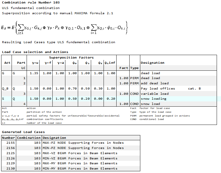
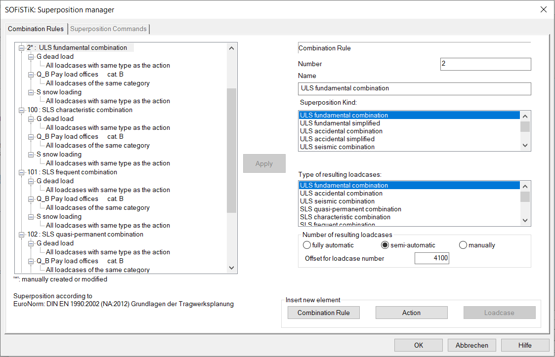
The National Annex Germany of the EN 1990 demands the equation 6.10 for the action combination of the ultimate limit state. Here the default equation can be used with COMB EXTR DESI. This corresponds to following MAXIMA input (DAT file second MAXIMA or SSD combination 2 or 103):
!*!Label Action Combinations
COMB NO 2 EXTR DESI BASE 4100 TYPE DESI TITL "ULS fundamental combination"
ACT TYPE G  PART G TITL "dead load"
!  LC NO                                              ! no definition for LC = use default: all load cases of the action G
ACT TYPE Q_B  PART Q TITL "Pay load offices cat. B"
!  LC NO -1                                           ! no definition for LC = use default: all load cases of the category B
ACT  TYPE S  PART Q TITL "snow loading"
!  LC NO 0                                            ! no definition for LC = use default: all load cases of the action S
Or in the SSD example:
Before defining the superposition values the output possibility ECHO CHCK for the most relevant values is input. It means that a full printout is done for the following most relevant values, whereby most relevant means: one value for MAX and one for MIN per each force here.
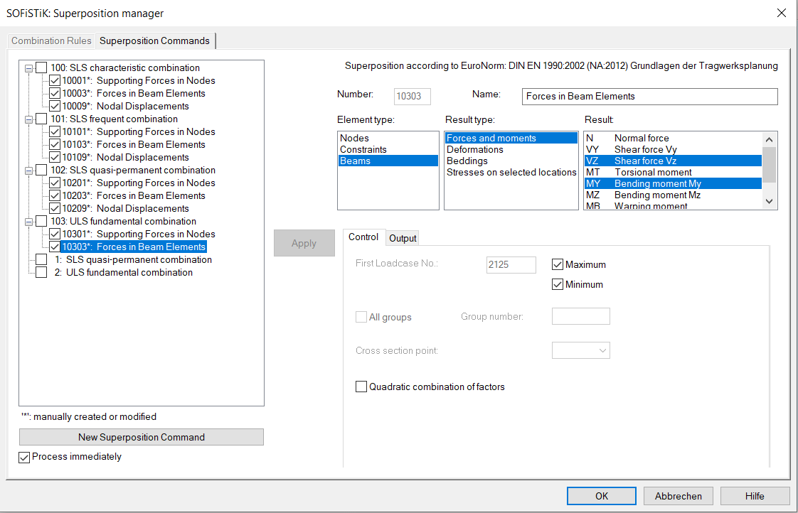
In the second part a superposition for the normal forces should be done in the cross section points Z+ or Z- (see also screenshot of the cross section above) for beam end no. 10005 (middle of the first span) or for beam end no. 10010 (middle support). OPT S means, that only for these points the values are calculated. If OPT S is not input, the superposition is done for all beam sections and the input of the beam number at FROM and beam position at X is only valid for the selected ECHO option ECHO LOAD,FACT - full printout. OPT S is not available in the SSD task ‘Superpositioning’.
!*!Label Superpositions
ECHO CHCK
SUPP COMB 2 EXTR MAMI ETYP BEAM TYPE VZ,MY TITL " Forces in Beam Elements"
SUPP COMB 2 EXTR MAMI ETYP NODE TYPE PZ TITL " Supporting Forces in Nodes"
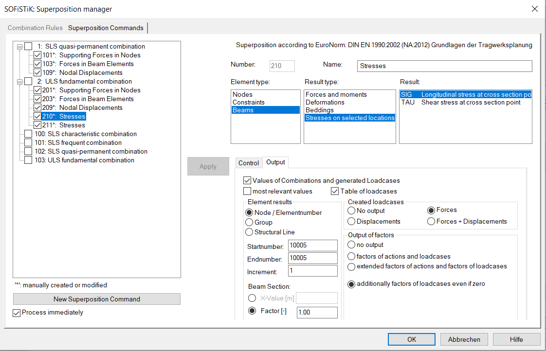
!*!Label Superposition Normal Stress in Cross Section Point Z+
ECHO CHCK NO
ECHO LOAD,FACT
SUPP COMB 2 EXTR MAMI ETYP BEAM TYPE SIG SELE Z+ FROM 10005 X 1[-] OPT S ! printout: end of beam no. 10005
SUPP COMB 2 EXTR MAMI ETYP BEAM TYPE SIG SELE Z- FROM 10010 X 1[-] OPT S ! printout: end of beam no. 10010
Or in the SSD example 2nd task ‘Superpositioning’:
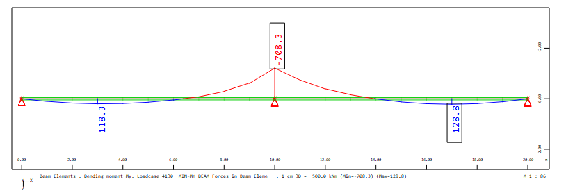
Finally, the full printout will be explained for the minimum bending moment My at middle support for the combination 2:

The first table shows the values of the initial load cases. In the second table ‘Determination of Sums and Leading Variable Action’ the calculated sums and the possible resulting factors are printed. Here the decision for the leading or accompanying action is shown with a * at the corresponding sum value:
Leading action is Q_B: Act Q_B: SumQ1 = -233.2999* SumQI = -163.3100
Accompanying action is S: Act S: SumQ1 = -93.3200 SumQI = -46.6600*
Hint
Please note, that the leading action is that with the largest difference between the two sums.
It follows the table of the determined load case combination with the determined factors for minimum MY. At least the resulting beam forces min MY = -708.3 kNm is shown in the table ‘Relevant Forces in Beam Elements’
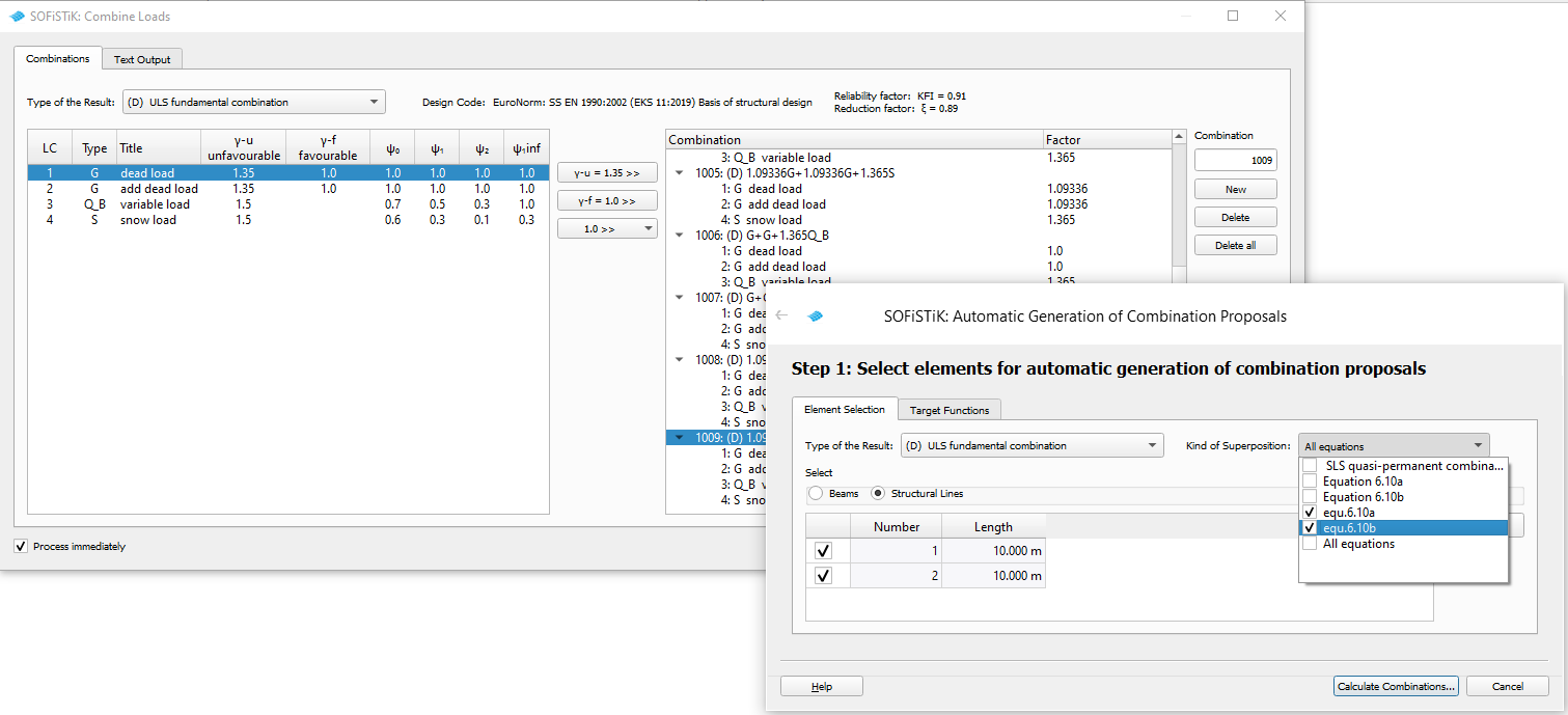
In the SSD file the task ‘Combine Loads’ is included. Here the resulting load combinations for the ultimate limit state are determined automatically via the button ‘Automatic’. A click on ‘Automatic’ opens a subdialog. For the determination of the load case combinations action combinations which are stored in the database should be selected. During the calculation a MAXIMA runs internally and then the found load case combinations are made available to the dialog for further processing.
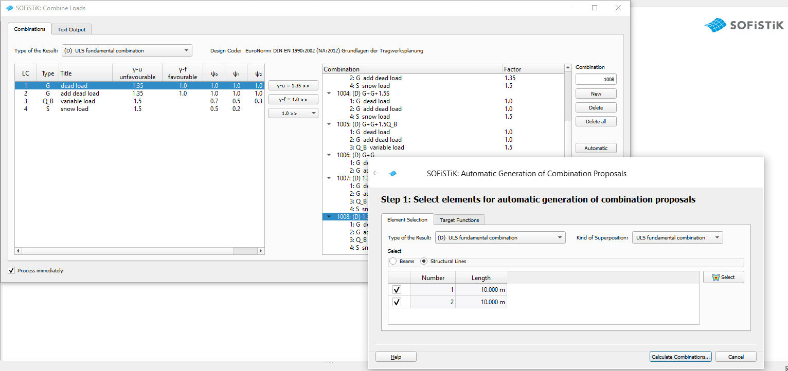
A detailed description of this internal process is available in the tutorial: Determination of Decisive Load Case Combinations with Superposition of Normal Stresses in Cross Section Points https://www.sofistik.de/documentation/2020/en/tutorials/superpositions/bb14-bockhold-vossen/superposition_bb14-bockhold-vossen.html
Second Example according to SS EN1992-2004 with the Particularities of the Equations 6.10a and 6.10b#
Files: ss_en1992-2004-cat A2_girder.dat and ssd2020-ss_en1992-2004-cat A2_girder.sofistik
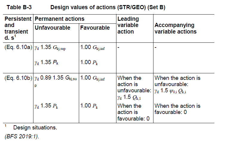
The selected building class for the design code is CAT A2 or in the SSD for buildings ‘Konstruktion og säkerhetsklass: A2 (Byggnader klass 2)’. Due to this definition the actions values and action combinations are generated automatically. The Swedish National Annex of the EN 1990 (EKS 11:2019) prescribes the use of the equations 6.10a and 6.10b for the fundamental combinations of the ultimate limit state. Here the reduction factor Xsi is given with 0.89 and the reliability (consequences class) factor Kfi called in this National Annex as Gamma-d with 0.91 for the safety class 2.
Literature: Boverket mandatory provisions amending the board’s mandatory provisions and general recommendations (2011:10) on the application of European design standards (Eurocodes) , EKS (BFS 2019:1 EKS 11)
After the definition of the material, the cross section and the system generation the actions and the loads are input in program SOFiLOAD. These input definitions are analogous to the first example according to DIN EN1992-2004.
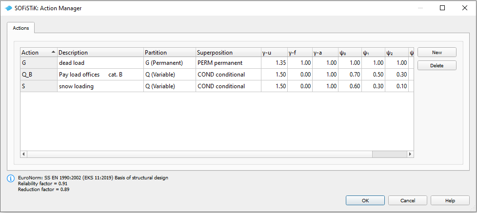
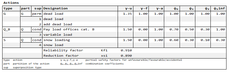
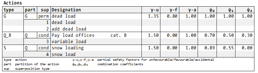
In the input of the actions in the SSD task ‘Action Manager’ and also in the printout table ‘Actions’ these two factors reduction factor Xsi and the reliability factor Kfi are shown:
In connection with the input of the loads it is possible to set ECHO ACT FULL for the printout table of the used actions and the corresponding load cases:
Hint
The reduction factor Xsi and the reliability factor Kfi are boxed values and stored in the database. They can be modified in the SSD task ‘System Information’ subdialog ‘boxed values’.
After the calculation of the single load cases the superpositions the preset action combinations and superpositions are used in the first MAXIMA run as described in the first example.
In the SSD the preset action combinations are shown in the task ‘Define Combinations’ and the superposition values are shown in the task ‘Superpositioning - preset superpositions’:
Please note, that all for a 3D system possible superposition values are preset. For this small system e.g. for the beam forces only Vz and My are interesting. In the SSD example only these values are set here manually.
Hint
If you want to get the complete MAXIMA (CADINP) input of the preset action combinations and superpositions, you can use the export from CDB to MAXIMA inside TEDDY or SSD (Button Database Tools -> Export to DAT).
The printout contains the general information about the action combinations and the table of the generated resulting load cases:
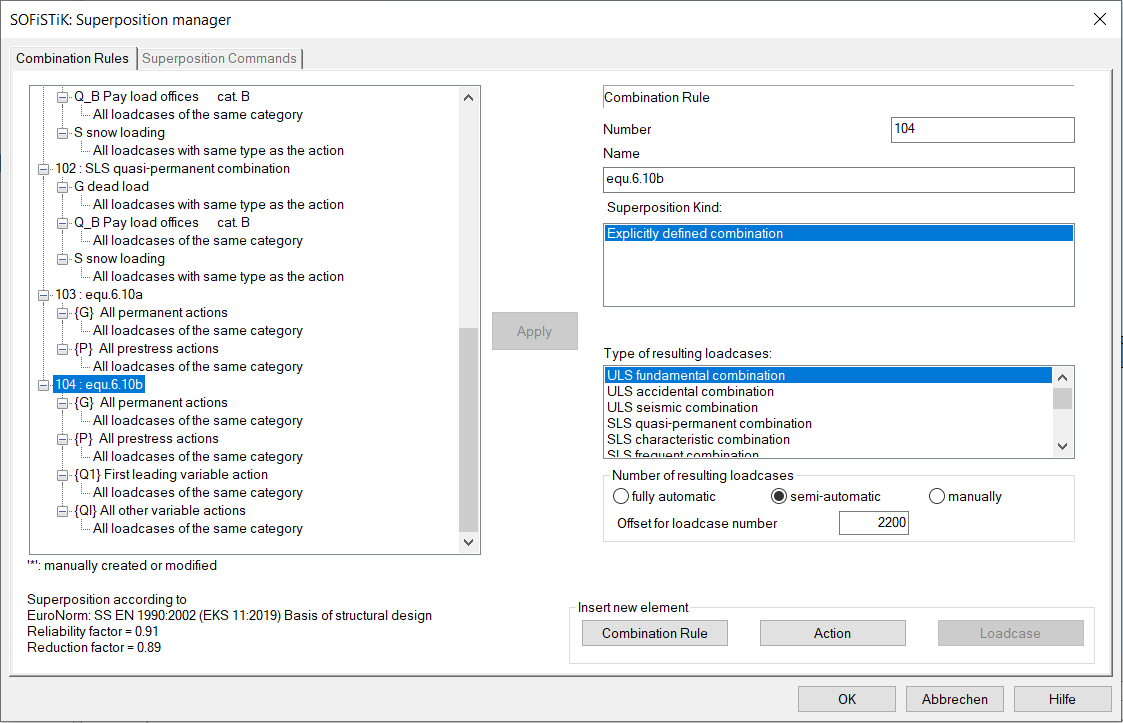
The National Annex Sweden of the EN 1990 demands the equation 6.10a and 6.10b for the action combinations of the ultimate limit state. Here these equations have to be defined with COMB EXTR EXPL. This corresponds to following MAXIMA input (DAT file second MAXIMA or SSD combination 2 and 3 or 105 and 106): The input ADD TYPE {Q1} demands the determination of the leading action and the input ADD TYPE {QI} the accompanying actions. The factors and factor combinations which should be used are defined with literals, e.g. KFG = reliability factor Kfi * Gamma-u or reliability factor Kfi * Gamma-f. The literals are described in the MAXIMA manual chapter 3.8 ADD – Actions for an Explicit Defined Combination
This procedure is absolutely necessary because the determination of the leading and accompanying actions depends on the superposition value and the position at the structure. The maximum bending moment My in the middle of two spans results due to a different leading action. Also the minimum bending moment My on the middle support has a leading and a accompanying action with different resulting load case combinations.
Hint
With this procedure it is possible to determine automatically the leading and accompanying actions by MAXIMA for each superposition value at all positions on the structure for any possible action combinations.
!*!Label Action Combinations
COMB NO 2 EXTR EXPL BASE 4100 TYPE DESI TITL "equation 6.10a"
ADD TYPE G  FACU KFG

COMB NO 3 EXTR EXPL BASE 4200 TYPE DESI TITL "equation 6.10b"
ADD TYPE G     FACU XKGU  FACF GAMF
ADD TYPE {Q1}  FACU KFG
ADD TYPE {QI}  FACU KFG0
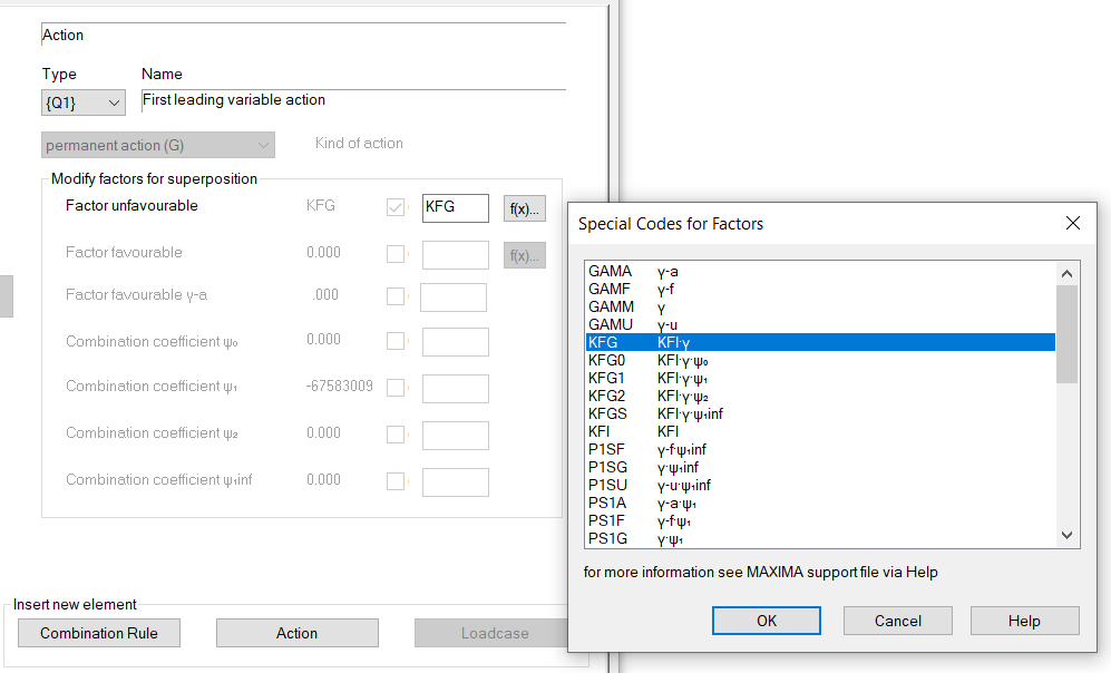
Or in the SSD example combination 3 manually defined via button Combination rule -> Insert explicit combination rule:
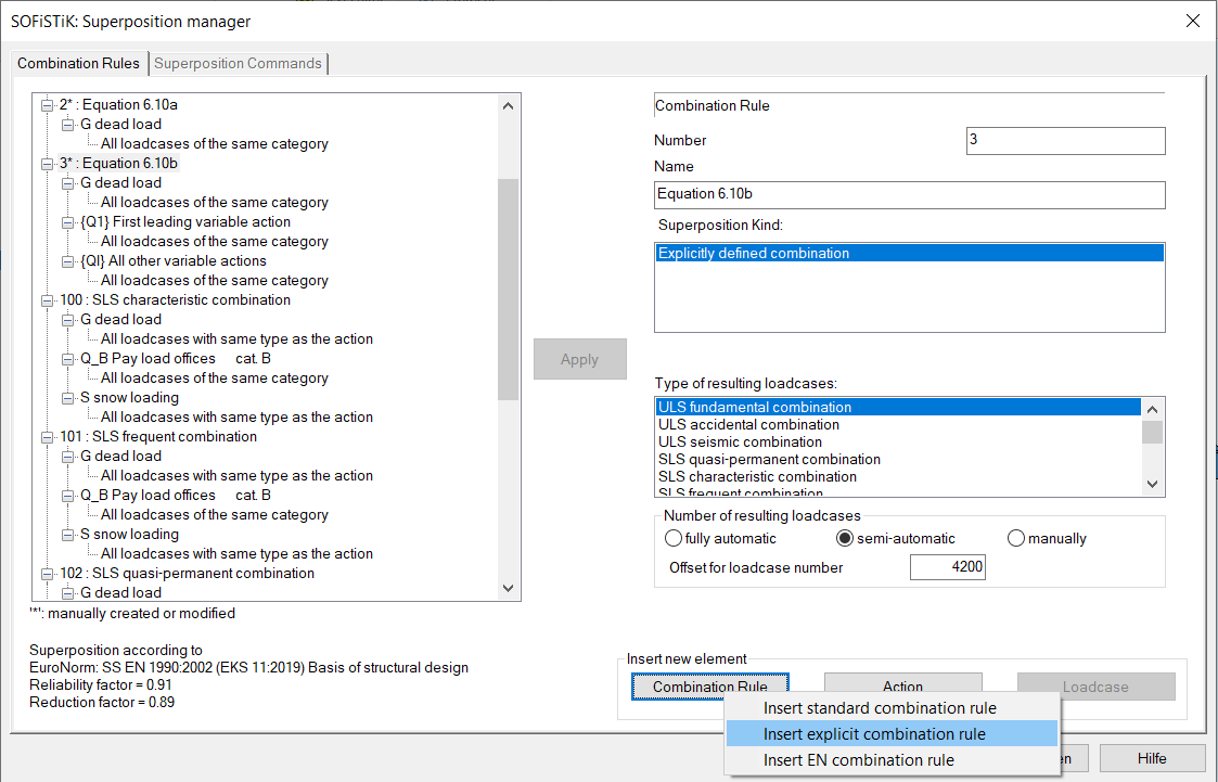
In the subdialog ‘Special Codes for the Factors’ the above described literals for the factors and factor combinations can be selected.
Before defining the superposition values the output possibility ECHO CHCK for the most relevant values is input. It means that a full printout is done for the following most relevant values, whereby most relevant means: one value for MAX and one for MIN per each force here.
In the second part a superposition for the normal forces should be done in the cross section points Z+ or Z- (see also screenshot of the cross section above) for beam end no. 10005 (middle of the first span) or for beam end no. 10010 (middle support). OPT S means, that only for these points the values are calculated. If OPT S is not input, the superposition is done for all beam sections and the input of the beam number at FROM and beam position at X is only valid for the selected ECHO option ECHO LOAD,FACT - full printout. OPT S is not available in the SSD task ‘Superpositioning’.
!*!Label Superpositions
ECHO CHCK
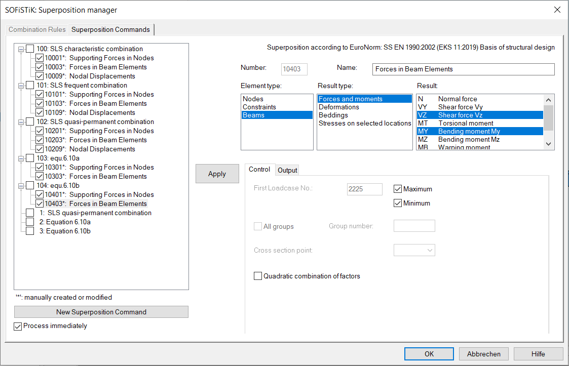
SUPP COMB 2 EXTR MAMI ETYP BEAM TYPE VZ,MY TITL " Forces in Beam Elements"
SUPP COMB 2 EXTR MAMI ETYP NODE TYPE PZ TITL " Supporting Forces in Nodes"
SUPP COMB 3 EXTR MAMI ETYP BEAM TYPE VZ,MY TITL " Forces in Beam Elements"
SUPP COMB 3 EXTR MAMI ETYP NODE TYPE PZ TITL " Supporting Forces in Nodes"
!*!Label Superposition Normal Stress in Cross Section Point Z+
ECHO CHCK NO
ECHO LOAD,FACT
SUPP COMB 3 EXTR MAMI ETYP BEAM TYPE SIG SELE Z+ FROM 10005 X 1[-] OPT S ! printout: end of beam no. 10005
SUPP COMB 3 EXTR MAMI ETYP BEAM TYPE SIG SELE Z- FROM 10010 X 1[-] OPT S ! printout: end of beam no. 10010
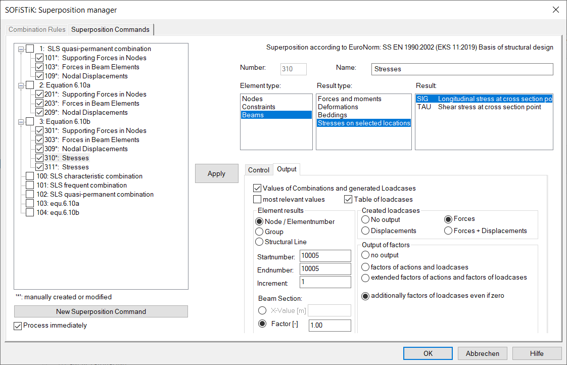
Or in the SSD example 2nd task ‘Superpositioning’:
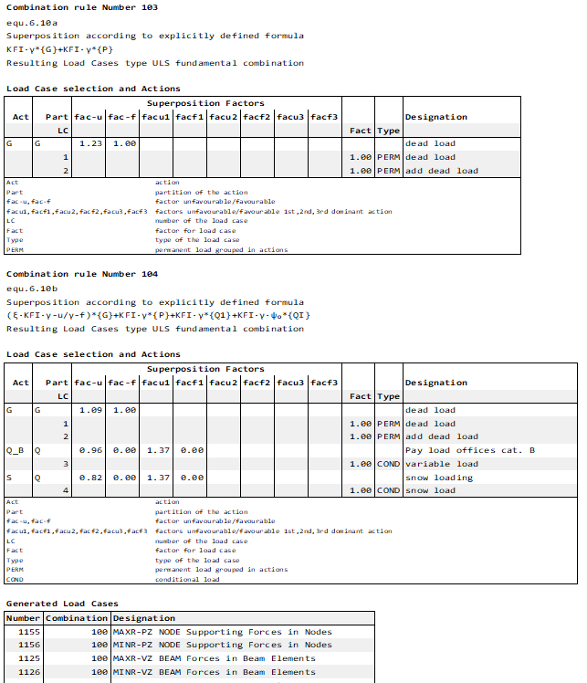
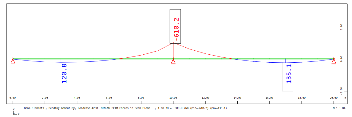
Finally, the full printout will be explained for the minimum bending moment My at middle support for the combination 3:
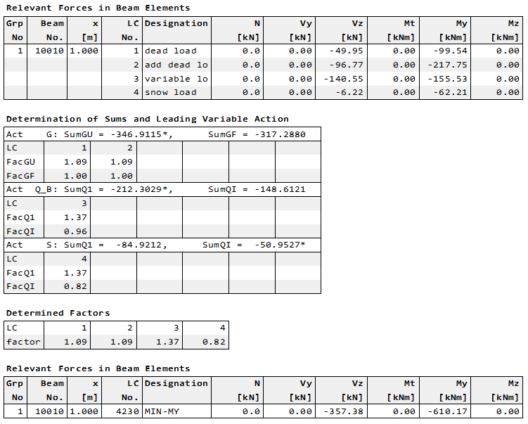
The first table shows the values of the initial load cases. In the second table ‘Determination of Sums and Leading Variable Action’ the calculated sums and the possible resulting factors are printed. Here the decision for the leading or accompanying action is shown with a * at the corresponding sum value:
Leading action is Q_B: Act Q_B: SumQ1 = -212.30 SumQI = -148.6121
Accompanying action is S: Act S: SumQ1 = -84.9212 SumQI = -50.9527*
Hint
Please note, that the leading action is that with the largest difference between the two sums.
It follows the table of the determined load case combination with the determined factors for minimum MY. At least the resulting beam forces min MY = -610.2 kNm is shown in the table ‘Relevant Forces in Beam Elements’
As in the first example in the SSD file the task ‘Combine Loads’ is included. Here the resulting load combinations for the ultimate limit state are determined automatically via the button ‘Automatic’. A click on ‘Automatic’ opens a subdialog. For the determination of the load case combinations action combinations which are stored in the database should be selected. During the calculation a MAXIMA runs internally and then the found load case combinations are made available to the dialog for further processing.
Third Example according to SIA 262 with the Particularities of SIA 260#
Files: sia262_girder.dat and ssd2020-sia262_girder.sofistik
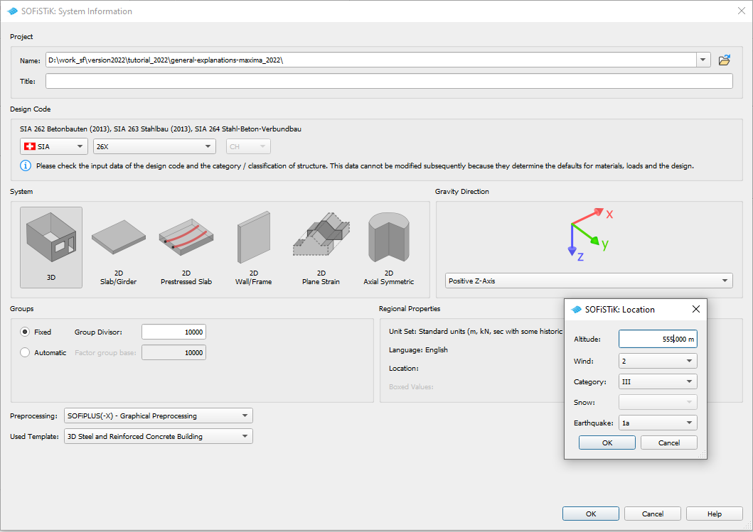
The Swiss code SIA 260 contains following particularity: The combination coefficients of the action snow are determined using formulas depending on the height over sea level according to table 2. In order to get the preset combination coefficients for snow it is necessary the input the height over sea lever at the definition of the design code:
Program AQUA record NORM with literal ALT
NORM 'SIA' '26X' ALT 555.[m] UNIT 0 ! ALT 555.[m] height over sea level
SSD task ‘System Information’ subdialog ‘Location’
After the definition of the material, the cross section and the system generation the actions and the loads are input in program SOFiLOAD. These input definitions are the analogous to the first example according to DIN EN199X-200X.
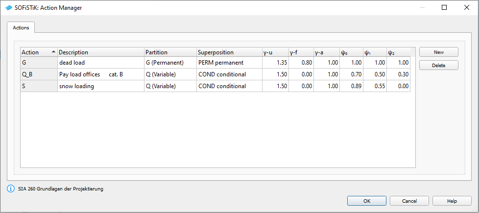
In the input of the actions in the SSD task ‘Action Manager’ and also in the printout table ‘Actions’ the combination coefficients for snow which were calculated by the program SOFiLOAD are shown:
In connection with the input of the loads it is possible to set ECHO ACT FULL for the printout table of the used actions and the corresponding load cases:
After the calculation of the single load cases the superpositions the preset action combinations and superpositions are used in the first MAXIMA run as described in the first example.
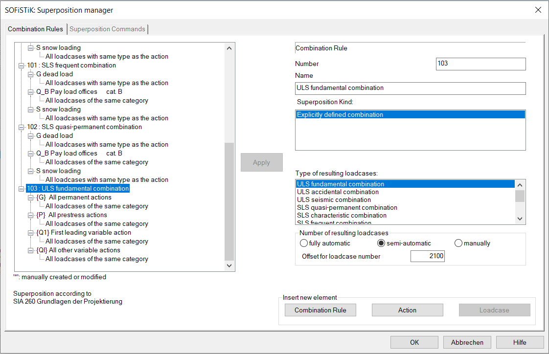
In the SSD the preset action combinations are shown in the task ‘Define Combinations’ and the superposition values are shown in the task ‘Superpositioning - preset superpositions’:
Please note, that all for a 3D system possible superposition values are preset. For this small system e.g. for the beam forces only Vz and My are interesting. In the SSD example only these values are set here manually.
Hint
If you want to get the complete MAXIMA (CADINP) input of the preset action combinations and superpositions, you can use the export from CDB to MAXIMA inside TEDDY or SSD (Button Database Tools -> Export to DAT).
The printout contains the general information about the action combinations and the table of the generated resulting load cases:
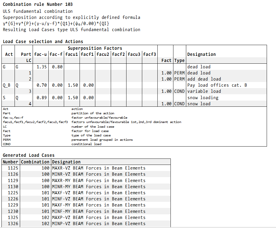
The SIA 260 demands the equation 16 for the action combination of the ultimate limit state. Here this equation has to be defined with COMB EXTR EXPL. This corresponds to following MAXIMA input (DAT file second MAXIMA or SSD combination 2 or 103):

!*!Label Action Combinations
COMB NO 2 EXTR EXPL BASE 4100 TYPE DESI TITL "ULS fundamental combination"
ADD TYPE G       FACU GAMU FACF GAMF           ! action G
ADD TYPE {Q1}    FACU GAMU FACF 0              ! leading action
ADD TYPE {QI}    FACU PSI0 FACF 0              ! accompanying actions
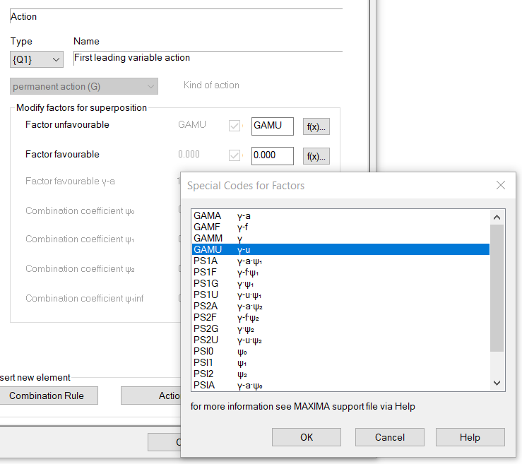
Or in the SSD example combination 2 manually defined via button Combination rule -> Insert explicit combination rule:
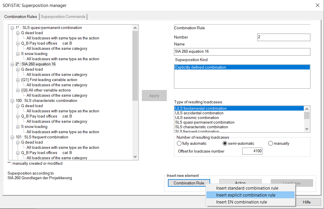
In the subdialog ‘Special Codes for the Factors’ the above described literals for the factors and factor combinations can be selected.
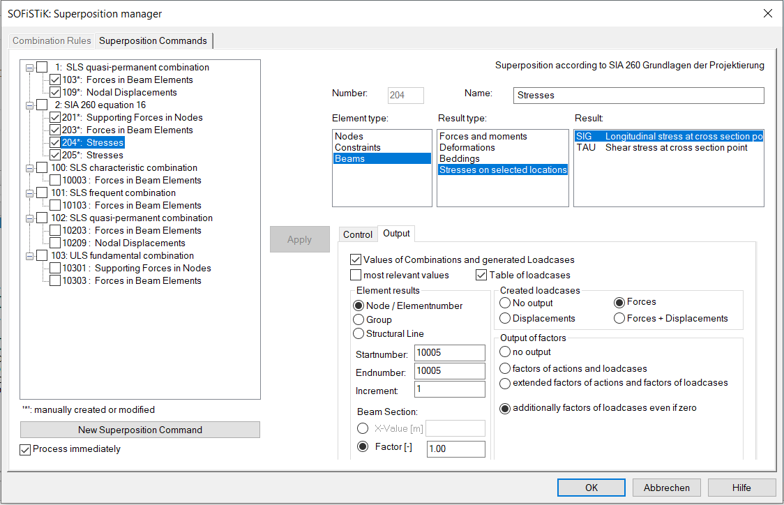
Before defining the superposition values the output possibility ECHO CHCK for the most relevant values is input. It means that a full printout is done for the following most relevant values, whereby most relevant means: one value for MAX and one for MIN per each force here.
In the second part a superposition for the normal forces should be done in the cross section points Z+ or Z- (see also screenshot of the cross section above) for beam end no. 10005 (middle of the first span) or for beam end no. 10010 (middle support). OPT S means, that only for these points the values are calculated. If OPT S is not input, the superposition is done for all beam sections and the input of the beam number at FROM and beam position at X is only valid for the selected ECHO option ECHO LOAD,FACT - full printout. OPT S is not available in the SSD task ‘Superpositioning’.
!*!Label Superpositions
ECHO CHCK
SUPP COMB 2 EXTR MAMI ETYP BEAM TYPE VZ,MY TITL " Forces in Beam Elements"
SUPP COMB 2 EXTR MAMI ETYP NODE TYPE PZ TITL " Supporting Forces in Nodes"

!*!Label Superposition Normal Stress in Cross Section Point Z+
ECHO CHCK NO
ECHO LOAD,FACT
SUPP COMB 2 EXTR MAMI ETYP BEAM TYPE SIG SELE Z+  FROM 10005 X 1[-] OPT S    ! printout: end of beam no. 10005
SUPP COMB 2 EXTR MAMI ETYP BEAM TYPE SIG SELE Z-  FROM 10010 X 1[-] OPT S    ! printout: end of beam no. 10010
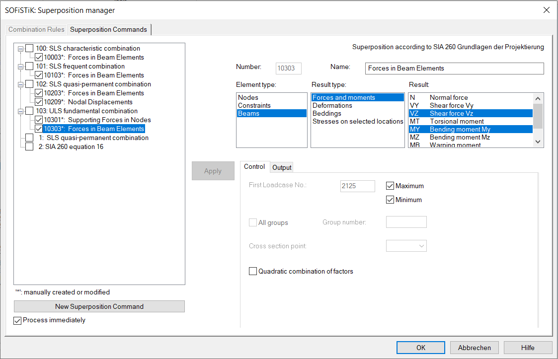
Or in the SSD example 2nd task ‘Superpositioning’:
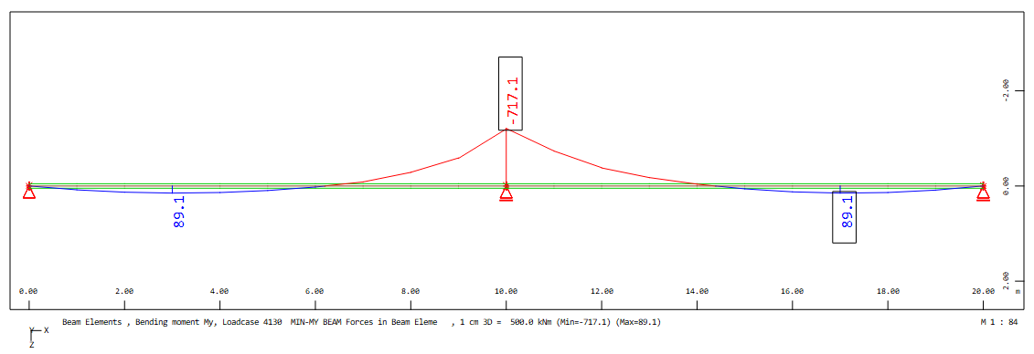
Finally, the full printout will be explained for the minimum bending moment My at middle support for the combination 2:
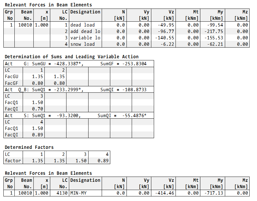
The first table shows the values of the initial load cases. In the second table ‘Determination of Sums and Leading Variable Action’ the calculated sums and the possible resulting factors are printed. Here the decision for the leading or accompanying action is shown with a * at the corresponding sum value:
Leading action is Q_B: Act Q_B: SumQ1 = -233.2999* SumQI = -108.8733
Accompanying action is S: Act S: SumQ1 = -93.3200 SumQI = -55.4876*
Hint
Please note, that the leading action is that with the largest difference between the two sums.
It follows the table of the determined load case combination with the determined factors for minimum MY. At least the resulting beam forces min MY = -717.13 kNm is shown in the table ‘Relevant Forces in Beam Elements’
As in the first example in the SSD file the task ‘Combine Loads’ is included. Here the resulting load combinations for the ultimate limit state are determined automatically via the button ‘Automatic’. A click on ‘Automatic’ opens a subdialog. For the determination of the load case combinations action combinations which are stored in the database should be selected. During the calculation a MAXIMA runs internally and then the found load case combinations are made available to the dialog for further processing.
Fourth Example according to ACI 318-14#
Files: us_aci318-14_girder.dat and ssd2020-us_aci318-14_girder.sofistik
The US customary units of the unit set 9 are used here. The cross section and the system are input in inch and the load in kip/ft.
The actions which are given in the ACI 318-14 are different to these of the EN 1990:
Dead load D
Live load L
Snow S
Important
In the different US design codes a number of action combinations are provided for the design. These action combinations depend on the in the system available actions and have a fixed unfavourable factor for the corresponding action. The safety concept of these design codes is completely different to the EN codes both on the load side and material side. In this tutorial the load side should be explained.
Literature: Building Code Requirements for Structural Concrete (ACI 318-14)
SOFiSTiK also offers preset actions and action combinations for this code ACI 318-14.
After the definition of the material, the cross section and the system generation the actions and the loads are input in program SOFiLOAD.
Hint
For the preset actions it is only necessary to input the action name. All other information about the preset actions are generated automatically.
+PROG SOFILOAD
HEAD Actions
ECHO ACT
ACT  'D' TITL "dead load"      ! default action D
ACT  'L' TITL "live load"      ! default action L
ACT  'S' TITL "snow load"      ! default action S
END
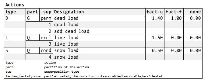
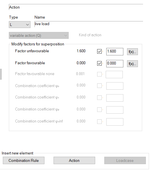
In the input of the actions in the SSD task ‘Action Manager’ and also in the printout table ‘Actions’ these two necessary preset factors for the unfavourable and favourable case are shown. Because the factors are changing in the given action combinations the changed factors are defined automatically in the preset combination.
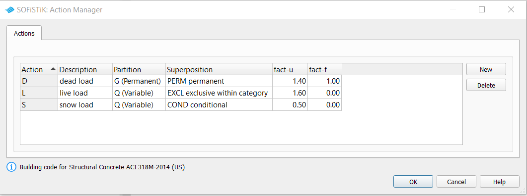
In connection with the input of the loads it is possible to set ECHO ACT FULL for the printout table of the used actions and the corresponding load cases:
After the calculation of the single load cases the superpositions are done in order to get the necessary design values (e.g. internal forces and moments, support reactions etc.).
In the first MAXIMA the preset action combinations and their preset superposition factors are calculated. In order to get these defaults only the following simple MAXIMA should run:
!*!Label Using preset action combinations
+PROG MAXIMA
HEAD Preset action combinations
CTRL INIT 1                          ! does not delete the combinations in the 2nd run
ECHO TABS YES
END
Or in the SSD the preset action combinations are shown in the task ‘Define Combinations’ and the superposition values are shown in the task ‘Superpositioning - preset superpositions’:
Please note, that all for a 3D system possible superposition values are preset. For this small system e.g. for the beam forces only Vz and My are interesting. In the SSD example only these values are set here manually. As already described all possible action combinations are preset for the general case. In this small project only the variable action L and S are used. Therefore, the superpositions were removed manually for the action combinations that were not required.
Hint
If you want to get the complete MAXIMA (CADINP) input of the preset action combinations and superpositions, you can use the export from CDB to MAXIMA inside TEDDY or SSD (Button Database Tools -> Export to DAT).
The printout contains the general information about the action combinations and the table of the generated resulting load cases:
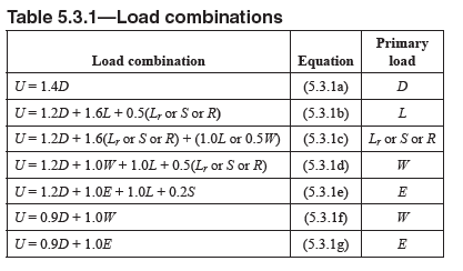
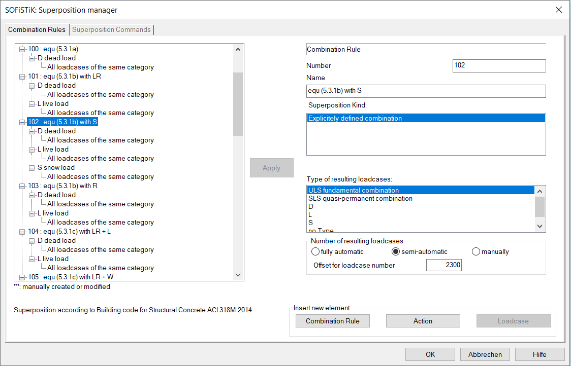
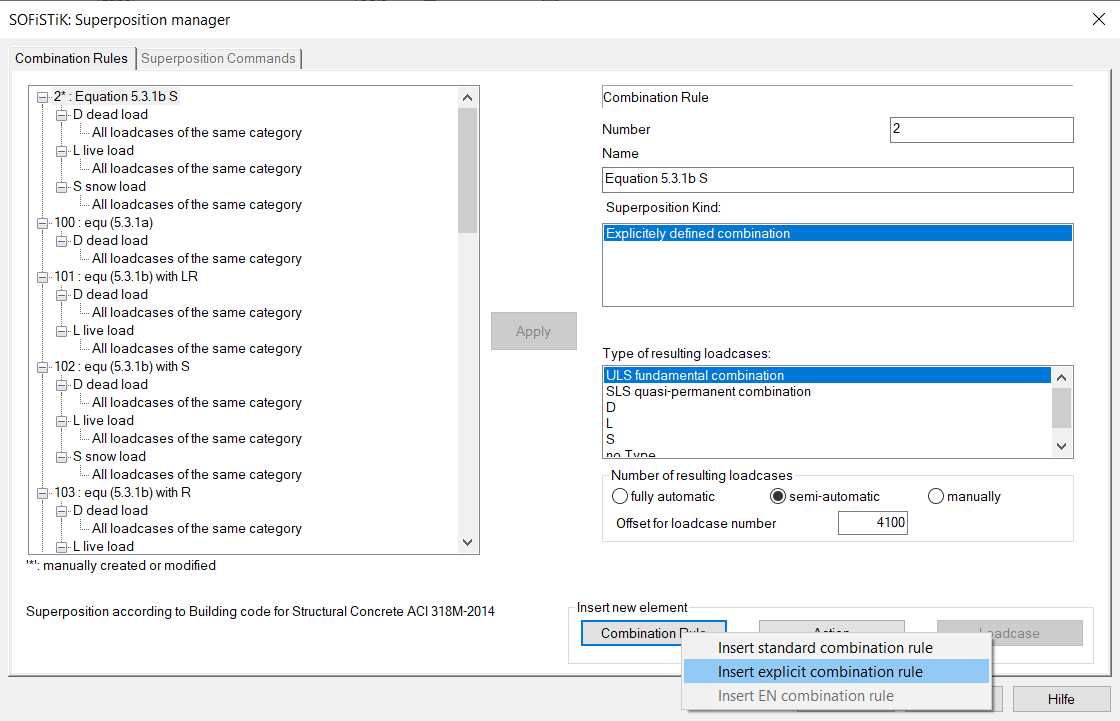
The ACI 318-14 demands several action combinations with different fixed factors. Here these equations have to be defined with COMB EXTR EXPL. As an example the equation (5.3.1b) with S is input manually (DAT file second MAXIMA or SSD combination 2 or 102), whereby the factors are defined as numerical value:
!*!Label Action Combinations
COMB NO 2 EXTR EXPL BASE 4100 TYPE DESI TITL "equation 5.3.1b"
ADD TYPE D  FACU 1.2  FACF 1.0
ADD TYPE L  FACU 1.6  FACF 0
ADD TYPE S  FACU 0.5  FACF 0
Or in the SSD example combination 2 manually defined via button Combination rule -> Insert explicit combination rule:
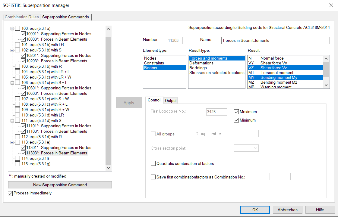
Before defining the superposition values the output possibility ECHO CHCK for the most relevant values is input. It means that a full printout is done for the following most relevant values, whereby most relevant means: one value for MAX and one for MIN per each force here.
In the second part a superposition for the normal forces should be done in the cross section points Z+ or Z- (see also screenshot of the cross section above) for beam end no. 10005 (middle of the first span) or for beam end no. 10010 (middle support). OPT S means, that only for these points the values are calculated. If OPT S is not input, the superposition is done for all beam sections and the input of the beam number at FROM and beam position at X is only valid for the selected ECHO option ECHO LOAD,FACT - full printout. OPT S is not available in the SSD task ‘Superpositioning’.
!*!Label Superpositions
ECHO CHCK
SUPP COMB 2 EXTR MAMI ETYP BEAM TYPE VZ,MY TITL " Forces in Beam Elements"
SUPP COMB 2 EXTR MAMI ETYP NODE TYPE UZ TITL " Nodal Displacements"
SUPP COMB 2 EXTR MAMI ETYP NODE TYPE PZ TITL " Supporting Forces in Nodes"
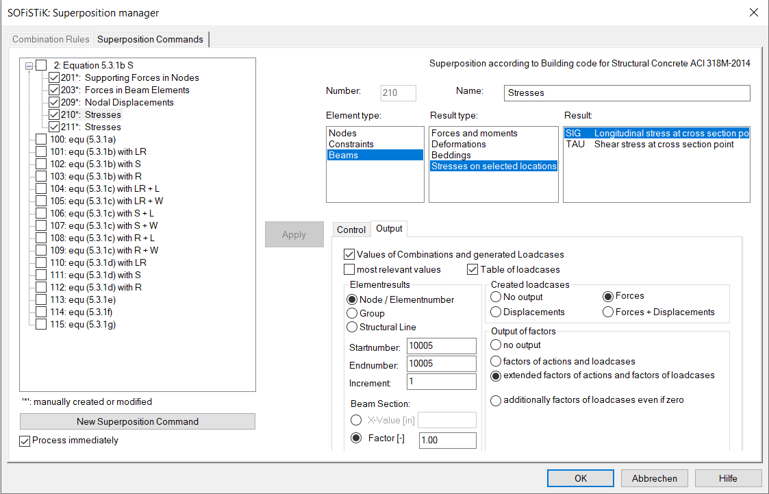
!*!Label Superposition Normal Stress in Cross Section Point Z+
ECHO CHCK NO
ECHO LOAD,FACT
SUPP COMB 2 EXTR MAMI ETYP BEAM TYPE SIG SELE Z+ FROM 10005 X 1[-] OPT S ! printout: end of beam no. 10005
SUPP COMB 2 EXTR MAMI ETYP BEAM TYPE SIG SELE Z- FROM 10010 X 1[-] OPT S ! printout: end of beam no. 10010
Or in the SSD example 2nd task ‘Superpositioning’:
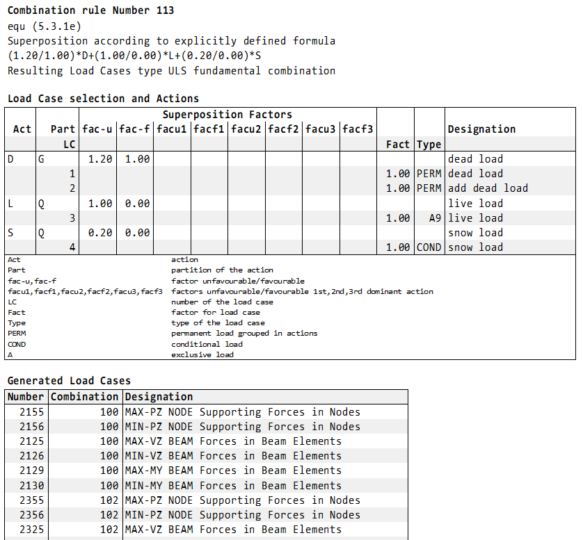
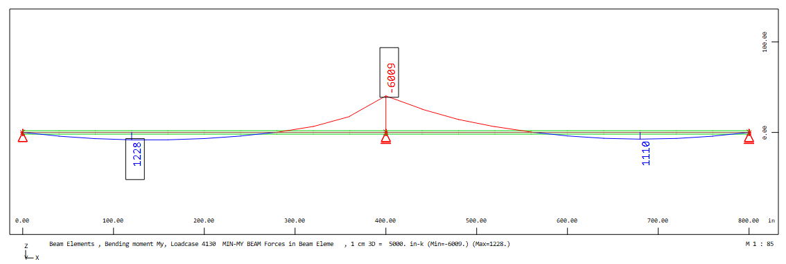
Finally, the full printout will be explained for the minimum bending moment My at middle support for the combination 2:
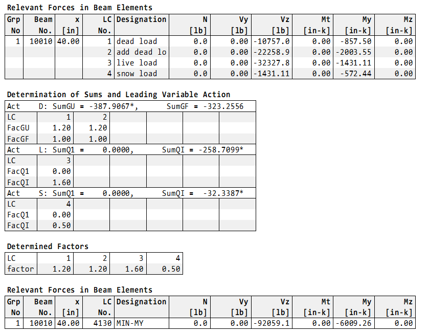
The first table shows the values of the initial load cases. In the second table ‘Determination of Sums and Leading Variable Action’ the calculated sums and the possible resulting factors are printed. This second table here not so important due to the safety concept of the ACI 318-14 where no leading or accompanying actions should be determined. The program MAXIMA decides only whether the single variable load cases are used.
It follows the table of the determined load case combination with the determined factors for minimum MY. At least the resulting beam forces min MY = -6009.26 in-k is shown in the table ‘Relevant Forces in Beam Elements’
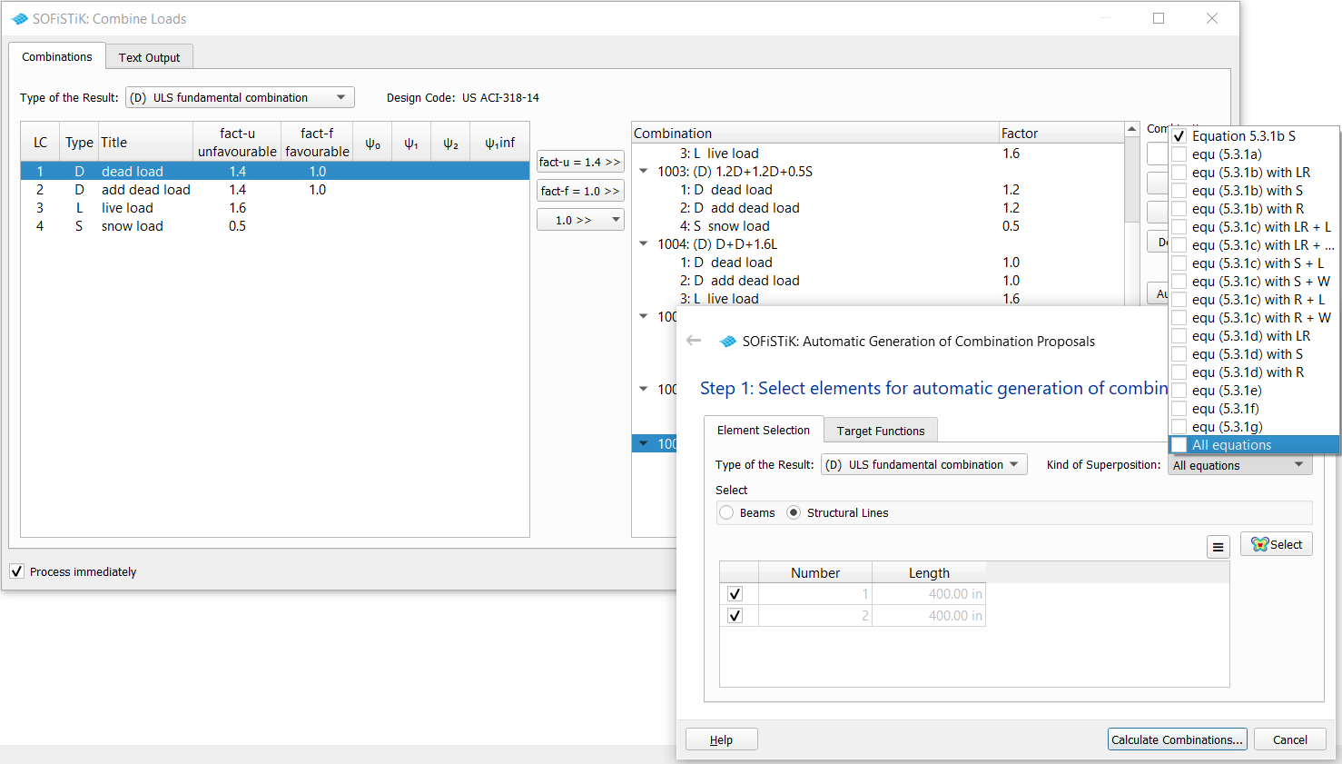
As in the first example in the SSD file the task ‘Combine Loads’ is included. Here the resulting load combinations for the ultimate limit state are determined automatically via the button ‘Automatic’. A click on ‘Automatic’ opens a subdialog. For the determination of the load case combinations action combinations which are stored in the database should be selected. During the calculation a MAXIMA runs internally and then the found load case combinations are made available to the dialog for further processing.
Remarks#
The several design codes and even the National Annexes of the EN 1990 provide different formulas for the action combinations. SOFiSTiK offers several options for the superposition automatically or manually using action combinations and for the determination of resulting load case combinations. It is the task of the engineer to check the used combination rules and randomly the results with the extensive output only for a specific element.
If you need a special solution for the topic of the combinations and superpositions of your project, contact us please with an email to support@sofistik.com.