Balanced Cantilever Bridge
Introduction
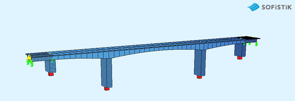
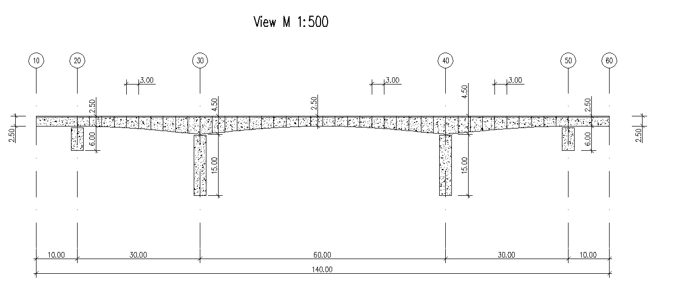
This tutorial deals with a simple 5-span balanced cantilever bridge. The analytical model of the bridge consists of beam elements.
Note
A basic SOFiSTiK knowledge is required for this tutorial. The standard workflow is explained inside the General Workflow description. Inside this tutorial we show only the project specific workflows, which are different from the basic workflow.
Objectives:
Starting a new project
Define Materials
Define Cross Sections
Generate System and Loads inside SOFiPLUS
Linear analysis
Live load analysis
Construction Stages
Design
Project Description
In order for your to follow the work-flow more easily, we split up the data files according to the different chapters. This enables you to start in the middle of the tutorial if necessary. The idea of this tutorial is to guide you through a balanced cantilever bridge project and introduce the general work-flow showing the necessary program tools and functions. All steps like modeling, loading, traffic loads, combinations etc. are simplified.
Note
If there are any hints of new tasks that have to be modified manually (new tasks named “Text Editor (Teddy)”) you find further information’s directly in those tasks. Please open data files related to the chapter.
Bridge Materials:
Number |
Title |
Strength |
|---|---|---|
1 |
Concrete bridge deck |
C 40/50 |
11 |
Concrete pier |
C 40/50 |
2 |
Reinforcement steel |
B 500 |
3 |
Reinforcement steel stirrups |
B 500 |
4 |
Prestressing steel |
Y 1570C |
Cross sections
Number |
Title |
Dimensions |
|---|---|---|
1 |
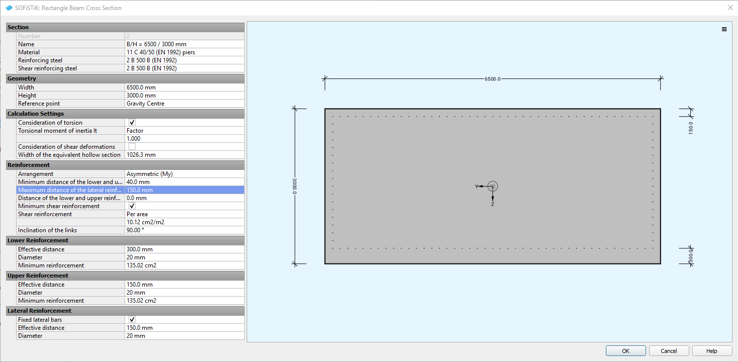
Column [mm] |
b/h=6500/3000 |
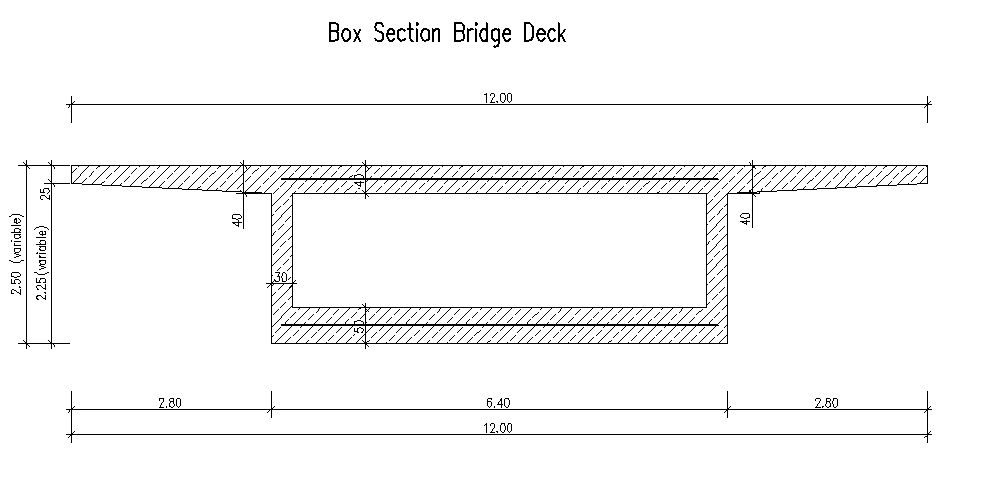
The bridge cross-section at station (10 m):
Construction stages
Stage Number |
Title |
|---|---|
11 Self-weight |
Activating piers (group 30 and 40) and group 1 |
15 Prestressing |
Prestressing in the Stage |
17 Creep in construction |
Activating creep and shrinkage |
19 Temporary load |
Activating temporary loads |
21 Self-weight |
Activating group 2 |
25 Prestressing |
Prestressing in the Stage |
27 Creep in construction |
Activating creep and shrinkage |
29 Temporary load |
Activating temporary loads |
31 Self-weight |
Activating group 3 |
35 Prestressing |
Prestressing in the Stage |
37 Creep in construction |
Activating creep and shrinkage |
39 Temporary load |
Activating temporary loads |
41 Self-weight |
Activating group 4 |
45 Prestressing |
Prestressing in the Stage |
47 Creep in construction |
Activating creep and shrinkage |
49 Temporary load |
Activating temporary loads |
51 Self-weight |
Activating group 5 |
55 Prestressing |
Prestressing in the Stage |
57 Creep in construction |
Activating creep and shrinkage |
59 Temporary load |
Activating temporary loads |
61 Self-weight |
Activating group 6 |
65 Prestressing |
Prestressing in the Stage |
67 Creep in construction |
Activating creep and shrinkage |
69 Temporary load |
Activating temporary loads |
71 Self-weight |
Activating group 7 |
75 Prestressing |
Prestressing in the Stage |
77 Creep in construction |
Activating creep and shrinkage |
79 Temporary load |
Activating temporary loads |
81 Self-weight |
Activating piers group 8 |
85 Prestressing |
Prestressing in the Stage |
87 Creep in construction |
Activating creep and shrinkage |
89 Temporary load |
Activating temporary loads |
91 Self-weight |
Activating piers group 9 |
97 Creep in construction |
Activating creep and shrinkage |
99 Temporary load |
Activating temporary loads |
101 Self-weight |
Activating group 15 |
107 Creep in construction |
Activating creep and shrinkage |
111 Self-weight |
Activating group 10, 20, 21 |
117 Creep in construction |
Activating creep and shrinkage |
121 Self-weight |
Activating group 22, 50, 60 |
125 Creep in construction |
Activating creep and shrinkage |
126 Creep in construction |
Activating creep and shrinkage |
130 Additional dead load |
Activating additional load |
137 Creep until t-infinite |
Activating creep and shrinkage t=30000 days |
Design code
This tutorial is based on Eurocode EN 1992.
Starting a new project
First we create a new SSD project and save it inside a project directory on your local computer. For further information see chapter Define Bridge Axis in General Workflow description.
Defining materials
Generate all necessary materials listed above. Follow the procedures explained in chapter Material Definition in General Workflow description.
Defining Cross Sections
In this project we do have only one standard cross section for the pier. Please generate a new rectangular cross section with the dimensions and material properties listed above. Follow the procedures explained in chapter in Cross Section Definition in General Workflow description.
The main bridge section will be defined graphically inside SOFiPLUS with the cross section editor.
Note
The deck cross section is varying in height along the length of the bridge. Instead of having to create many cross sections with different heights, a variable is assigned to the height which is varied along the length of the bridge. This variable will be defined within the bridge axis definition in SOFiPLUS. Therefore we recommend to create the bridge axis with all settings first.
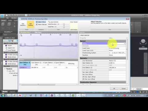
Pre-stressing systems
Please generate a new prestressing system number 1, with a VSL 6-7 multistrand system, see picture below.
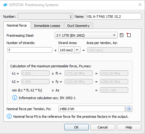
Follow the procedure explained in chapter Prestressing System in General Workflow description.
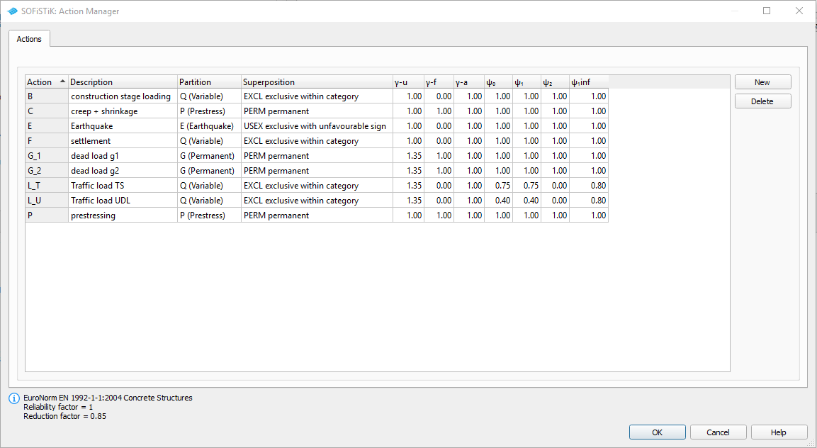
Actions
Before we define any load, we must define all necessary actions within the SSD ” Action Manager”. In our bridge example we need the following actions. (click on the figure to see it in full size).
System Generation in SOFiPLUS
The bridge geometry will be defined using the CABD concept inside SOFiPLUS. For that we will work through the following steps:
Define main bridge axis
Define placements along the bridge axis for supports and between all bridge segments
Define variables (will be used for the main cross section)
Generate master cross section within Cross Section Editor
Generate structure lines representing the main bridge construction
Use the Cross Members Editor to generate the support construction containing springs and couplings
Make a final check of the system and align elements if necessary
The following videos will show the main steps to generate the system.
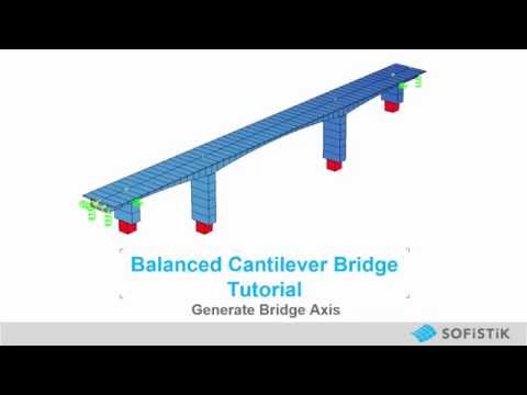
Generate Bridge Axis
The following video will show the axis generation workflow.
Generate Master Cross Section
The following video will show cross section generation workflow within the cross section editor.
System Generation
The following video will show the system generation workflow.
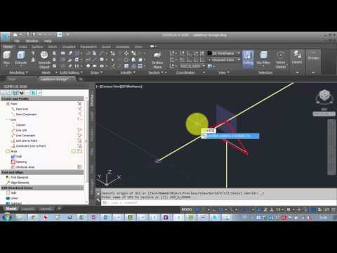
Tendon Generation
The following video will show tendon generation workflow.
Hint
Please note that in the example file, the tendons are defined via text input (for prestressing in stages). The video just shows the workflow how to generate tendons (for curvature loading).
Loads
Before we define any load, we must define all necessary actions within SOFiPLUS. In our bridge example we need the following actions and load cases:
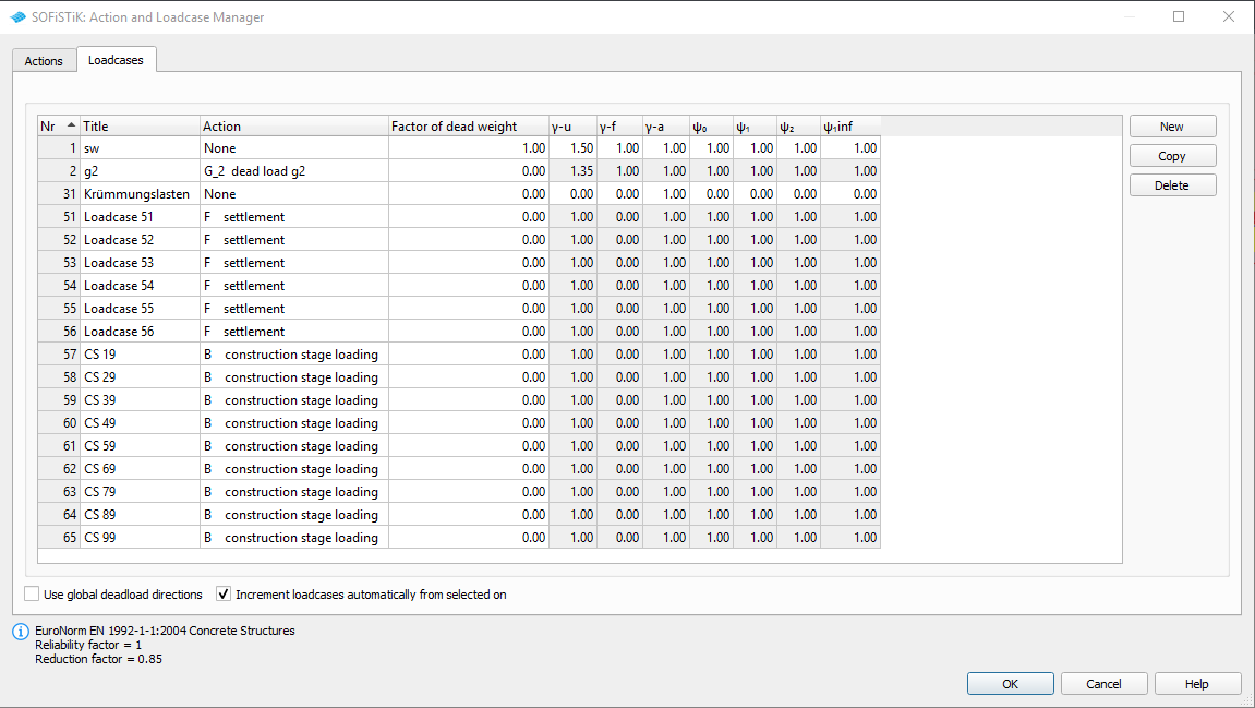
After defining the load cases we generate the loads in SOFiPLUS. First we select an element related line load. Defining the load we select the structural lines and define a line load of 10 kN/m. In support axis (group 20, 30, 40, 50) we define a settlement WZZ = 10 mm and for groups (10 and 60) we define WZZ=5 mm. Save the loads within load-cases 51-56.
Warning
Load cases which will be used later on inside the CSM should be saved within the action container NONE. With this concept the load cases will not be used twice in case the user defines his own combination rules using actions only!
For further processing including the necessary temperature combinations please see the chapter Define Actions and Loads in General Workflow description.
Linear Analysis
The linear analysis will be processed automatically for all defined loads. Therefore the selection must be done manually. Please see the chapter Linear Analysis in General Workflow description.
Generate Envelope from Traffic Loads
As already explained in the general workflow it is necessary to run at least one linear load case before evaluating the traffic loads with the influence line method. We recommend to do this analysis before the construction stage analysis to use the full developped stiffnes matrix from the complete bridge.
For a general description of the input workflow please see also the chapter Traffic Loads in General Workflow description. For our little example we have a bridge with a lane width of 3.0 m. First you select an existing bridge axis and define the width of the traffic lane and bridge. The program will automatically generate all possible lanes.
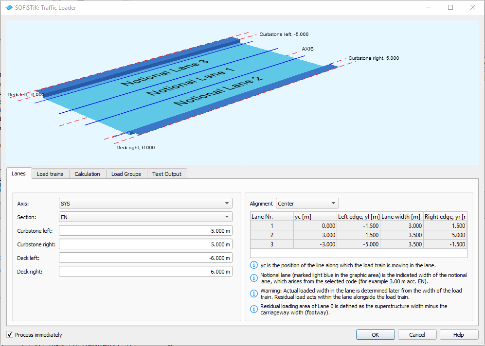
Next you define the load trains and the desired results. In our case we are interested only in the beam results for further design of the cross sections.
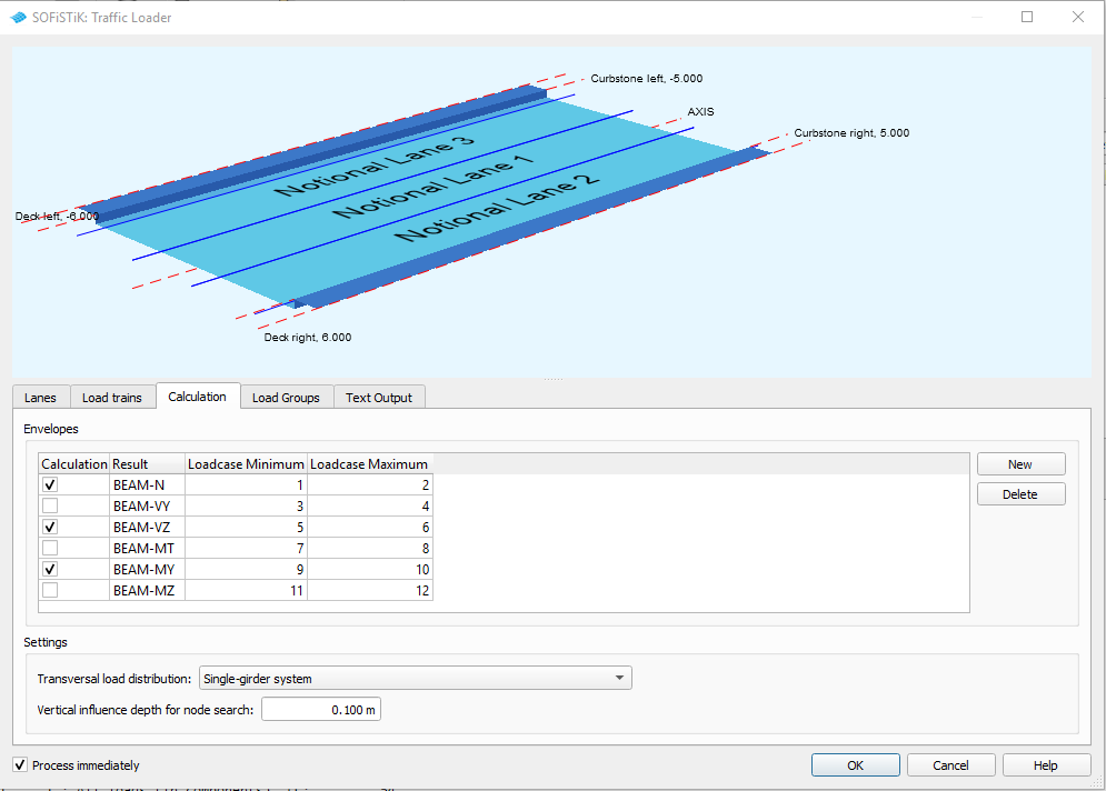
For the results it is necessary to define different load groups and evaluation cases. Usually it is convenient to separate the results for tandem axes and udl loads. The evaluation results will be saved again in predefined action container.
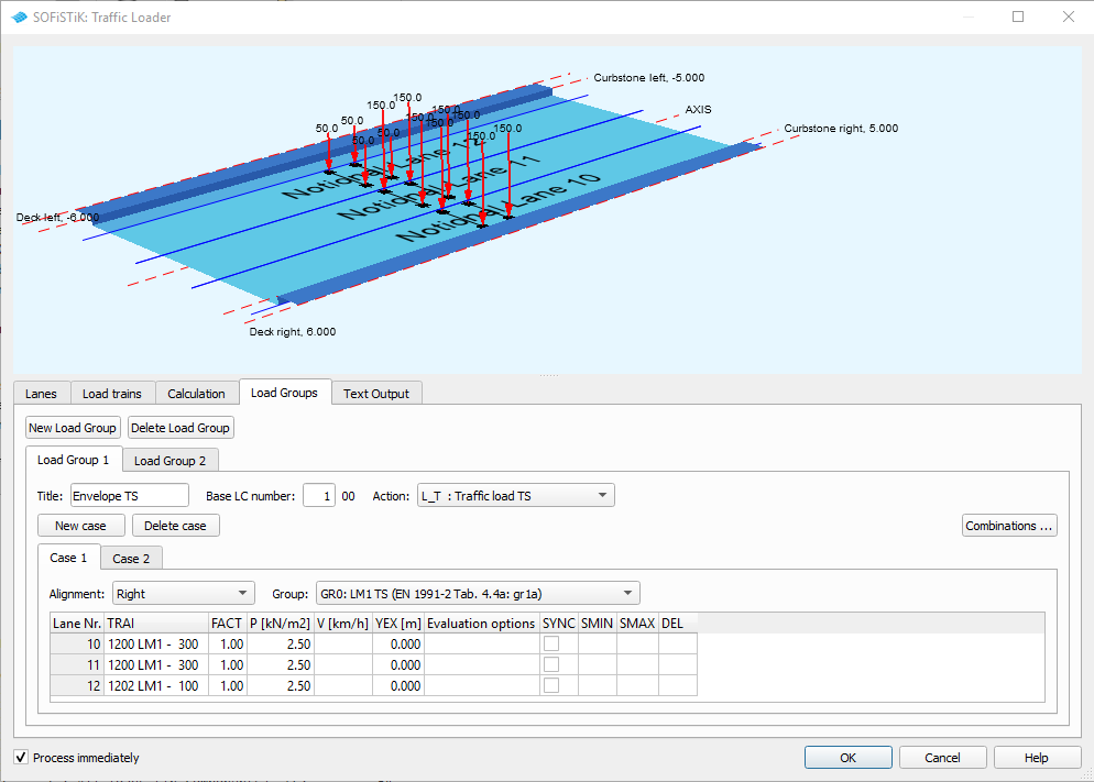
The loads on the footway will be defined as an extra evaluation case inside the UDL load group. In that case we need special combinations from UDL and Footway loads. Simply use the combination button inside the dialogue and generate the combinations. After the input is correct and finished you may close the dialogue and process immediately the analysis. Again we recommend to add a task “Interactive Graphic” to display the important results.
Define Construction Stages
For post tensioned concrete bridge we need the construction stages for the evaluation of different cross section properties based on the open and filled ducts for the tendons as well as for creep and shrinkage analysis. Insert the SSD tasks “CSM” and fill in the stages as defined in table Construction Stages above.
For our example the following input must be done inside the task “CSM - Construction Stage Manager”.
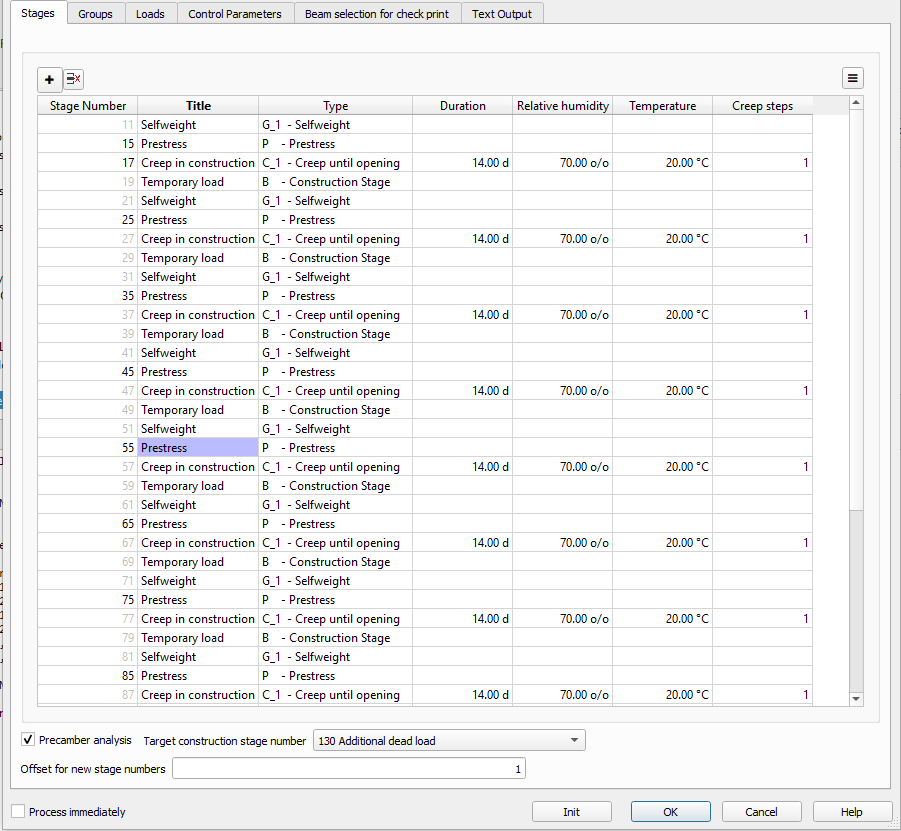
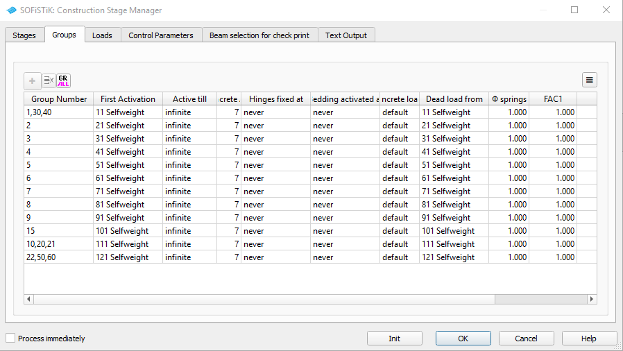
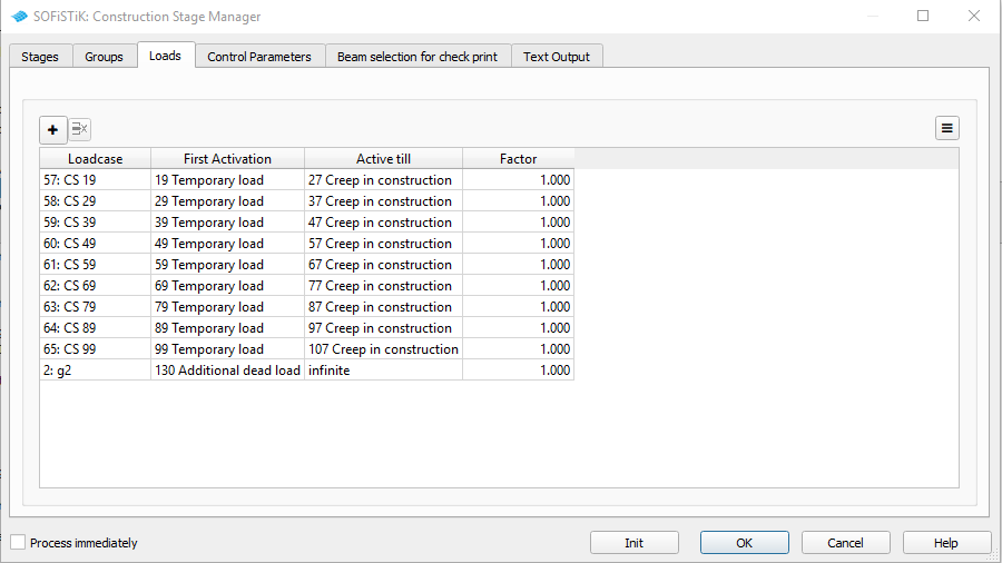
For further explanations please see also the chapter Construction Stages in General Workflow description and our CSM_1.pdf manual.
Combinations
Please follow the explanations of chapter Combinations and Superpositioning from the General Workflow description.
Design
Please follow the explanations of chapter Design Checks from the General Workflow description.
Documentation
For the final documentation, you can collect all single reports and generate a complete document. Please follow the explanations of chapter Generate Report from the General Workflow description.


