Double T-Beam Post Tensioned Concrete Bridge
Introduction
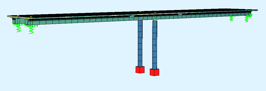
This tutorial deals with a simple 2-span post tensioned concrete double T-beam bridge. The analytical model of the bridge consists of beam elements and a slab to connect the two T-beams. The piers are modelled with beam elements as well.
Note
A basic SOFiSTiK knowledge is required for this tutorial. The standard workflow is explained inside the General Workflow description. Inside this tutorial we show only the project specific workflows, which are different from the basic workflow.
Objectives
The main objective in this tutorial is to show the workflow using a “hybrid” model, with beams and slabs for the bridge deck. The system generation will be done inside SOFiPLUS. All the other objectives from starting a project up to performing analysis and design are the same as described in the standard workflow. Here we will focus on the settings necessary for a “hybrid” bridge system.
Project Description
In order for you to follow the workflow more easily, we have split up the data files according to the different chapters. This enables you to start in the middle of the tutorial if necessary. The idea of this tutorial is to guide you through a simple DTB (Double-T-Beam) post tensioned concrete bridge project, showing the important program tools and functions for this type of bridge.
Bridge Axis:
The following table shows the main spans and stations for the axis definition.
Spans [m] |
1,00 |
- |
32,50 |
- |
32,50 |
- |
1,00 |
Stations [m] |
10.0 |
11,00 |
- |
43,50 |
- |
76,00 |
77,00 |
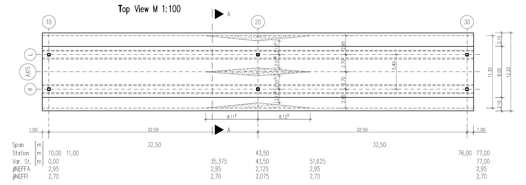
Along the bridge axis we will use a variable for the non-effective parts of the cross sections. Please see the following table with the necessary input values.
Station [m] |
0.000 |
35.375 |
43.500 |
51.625 |
80.000 |
#NEFFA [m] |
2.950 |
2.950 |
2.125 |
2.950 |
2.950 |
#NEFFI [m] |
2.700 |
2.700 |
2.075 |
2.700 |
2.700 |
Bridge Materials:
The following table show the necessary materials. As you can see, we are using different material numbers for bridge deck and column, although the concrete material is the same. This is a common setting inside SOFiSTIK to be able to split up the results for a better overview.
Number |
Title |
Strength |
|---|---|---|
1 |
Concrete pier |
C 40/50 |
2 |
Reinforcement steel pier |
B 500 |
11 |
Concrete t-beam |
C 40/50 |
12 |
Reinforcement t-bea |
B 500 |
14 |
Prestressing steel t-beam |
Y 1570C |
21 |
Concrete bridge deck |
C 40/50 gam=0.0 |
22 |
Reinforcement steel bridge deck |
B 500 |
Construction stages
Stage Number |
Title |
|---|---|
10 |
Selfweight structure |
11 |
Prestress of superstructure |
15 |
Creep + Shrinkage |
20 |
Further permanent loads (for example asphalt) |
25 |
Creep + Shrinkage until traffic opening |
35 |
Creep + Shrinkage from traffic opening until t=oo |
List of Element Groups
ID |
Title |
Element Type |
|---|---|---|
1 |
T-Beam left side: Axis-L |
BEAM |
2 |
T-Beam right side: Axis-R |
BEAM |
3 |
Area Elements Bridge Deck |
QUAD |
10 |
Support Elements Axis 10 |
SPRING, CONSTRAINT |
20 |
Support Elements Axis 20 |
BEAM, SPRING, CONSTRAINT |
30 |
Support Elements Axis 30 |
SPRING, CONSTRAINT |
Design code
This tutorial is based on Eurocode DIN EN 1992.
Starting a new project
First we create a new SSD project and save it inside a project directory on your local computer. For further information see chapter Define Bridge Axis in General Workflow description.
Defining materials
Generate all necessary materials listed above. Follow the procedures explained in chapter Material Definition in General Workflow description.
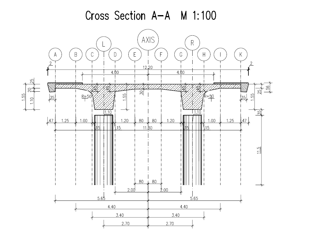
Defining Cross Sections
In this project we have only one standard cross section for the pier. Please generate a new rectangular cross section with the dimensions and material properties listed above. Follow the procedures explained in chapter in Cross Section Definition in General Workflow description.
The main bridge section will be defined graphically inside SOFiPLUS with the cross section editor.
Note
For the main bridge section we want to use a variable for the non effective parts of the cross sections. This variable will be defined within the bridge axis definition in SOFiPLUS. Therefore we recommend to create the bridge axis with all settings first.
Pre-stressing systems
Please generate a new prestressing system number 1, with a VSL 6-19 multistrand system, see picture below.
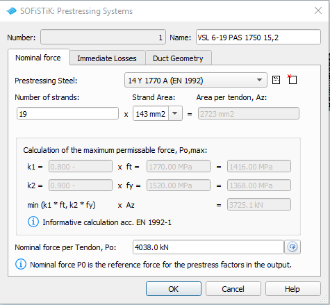
Follow the procedure explained in chapter Prestressing System in General Workflow description.
System Generation in SOFiPLUS
The bridge geometry will be defined using the CABD concept inside SOFiPLUS. For that we will work through the following steps:
Define main bridge axis
Define placements along the bridge axis
Define variables (will be used for the main cross section)
Define secondary axes with an offset. These axes are important for the bridge deck generation
Generate master cross section within Cross Section Editor
Generate structure lines representing the main T-beams
Generate structure areas representing the bridge deck
Use the Cross Members Editor to generate the support construction, containing piers, springs and couplings
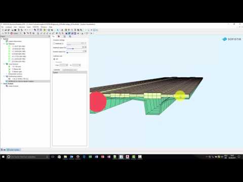
Make a final check of the system and align elements if necessary
The following videos will show the main steps to generate the system.
Generate Bridge Axis
First of all we define the main bridge axis, with placements, variables and secondary axes.
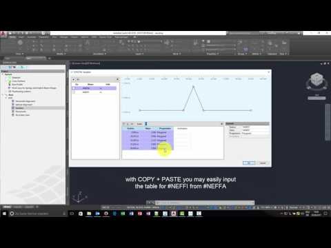
Generate Master Cross Sections
For both T-beams we will define master cross seections inside SOFiPLUS. These master cross sections conatin the variables #NEFFA and #NEFFI for the noneffective parts. For that We are using cartesian references.
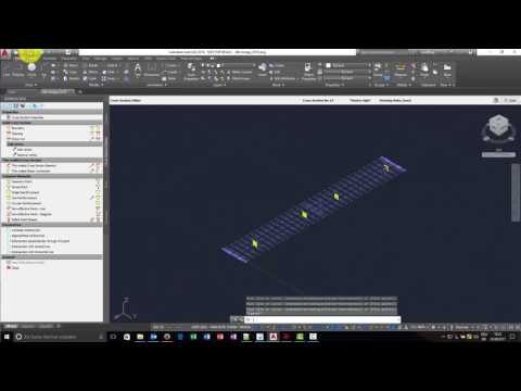
Generate Main T-Beams
First we define the main T-beams. To do so, we simply switch of all secondary axis layers we do not need. In our case we keep the main axis and the secondary axis L and R. Then we open the command “Line” from tab “Structural Lines” in SOFiPLUS and create the T-beams between all placements of Axis-L and Axis-R.
Generate Slab
In the next step we will create the bridge deck. As the slab thickness varies over the width of the bridge we need to create that in several steps.
we switch on the necessary secondray axes
we create structural areas of group 3, with a constant thickness of 300 mm and with no geometric changes using the command “Segement on axis”
after that we modify the borders of the structural areas. With the AutoCAD feature “Isolate > Hide Objects” we can easily select the areas for the modification process
in the last step we change the geometry of the area elements: “Structural Area > Element Alingment > positive local z”
Note
In our system the area elements are supported by the T-beams. This means, that the span width in cross direction neglect the thickness of the t-beam web and results in a larger span width. One option to solve this problem is to define structural lines at the corner of the T-beam web and create a coupling between this lines and the T-beam. In our case we would create a coupling from axes AXIS-C, AXIS-D to AXIS-L and from AXIS-G and AXIS-H to AXIS-R. the following video will NOT show this modelling concept.
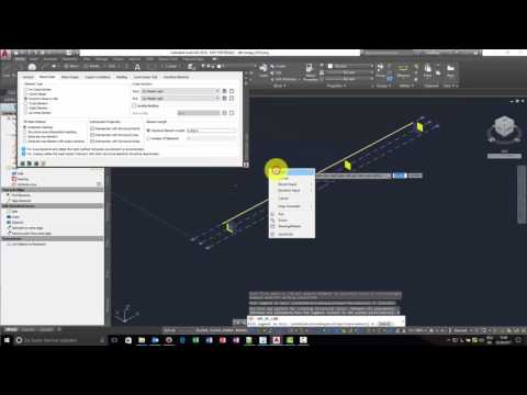
Generate Support Structure
All supports will be created inside the Cross Members Editor. This allows you to work in the y-z-plane of the placement. All elements will be connected directly to the placement.
Generate Prestressing
Please follow the procedures explained in our tutorial Post Tensioned Concrete Beam Bridge .
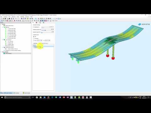
Lineare Analysis
All loads acting on the final bridge will be analysed with the task “Linear Analysis”. In our case we have a system with beam and area elements. This means, the stiffness of the area elements in the x-direction of the bridge are overlapping the stiffness of the t-beams. Also the self weight of the area elements are overlapping the T-beams. The self weight problem can be easily solved as we use a different concrete material with gamma = 0.0 kN/m³ for the bridge deck. See also chapter “Bridge Materials”. The stiffness of the area elements can be reduced in the local x-direction by a special option of module ASE. The record GRP2 with the literals QUEA and QEMX allows us to reduce the membrane and bending. With QUEA the E·A part of the QUAD elements and with QEMX the elastic modulus of QUAD elements can be modified in local x-direction. For that reason, we need to modify the task “Linear Analysis”. First we convert this task into a “User Task”. Then we add the new record GRP2 QUEA 0.01 QEMX 0.01 into the ASE module.
The input is printed below:
+PROG ASE $ Linear Analysis
HEAD Calculation of forces and moments
PAGE UNII 0
ECHO FULL FULL $ extensive output of text lists
CTRL OPT WARP VAL 0
CTRL OPT SPRI VAL 12
$ add record GRP2 to modify stiffness of QUAD elements
GRP2 NO 3 QUEA 0.001 QEMX 0.001 $ Reduce stiffness for bridge deck group 3
$ select loadcases to be analysed
LC 1,2
END
Construction Stage Manager
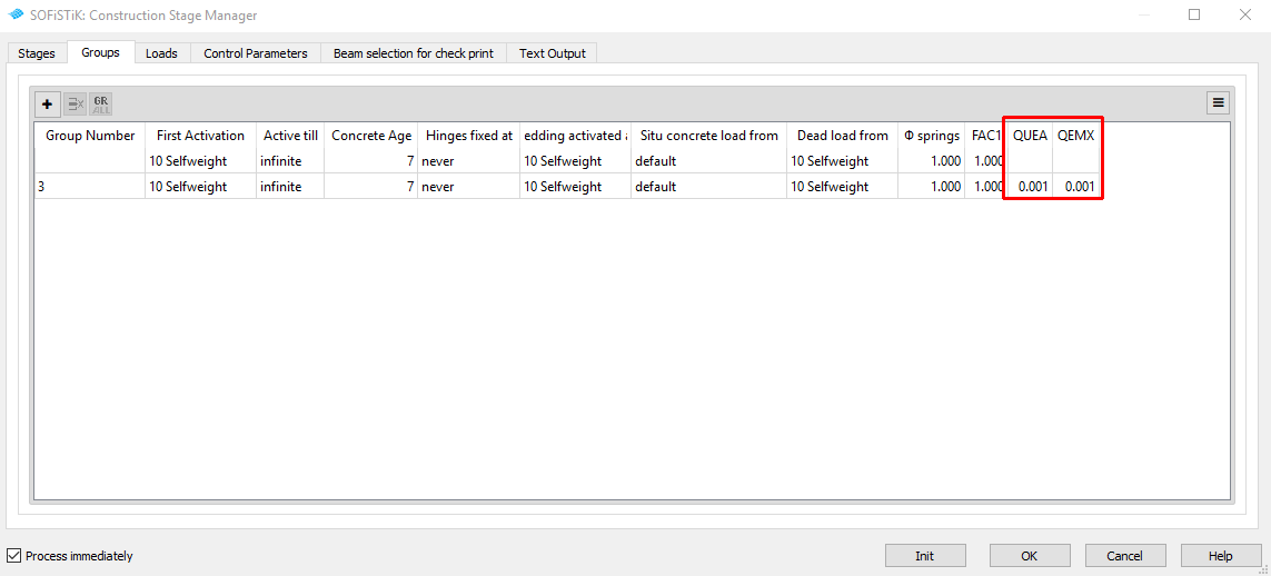
The task “Construction Stage Manager” will be used as usual. Simply add this task and define all necessary stages. Inside the tab “Groups” it is necessary to create a new line for the bridge deck area elements, which is group 3 in our example. As done in the task “Linear Analysis” we need to reduce the stiffness properties of these elements.
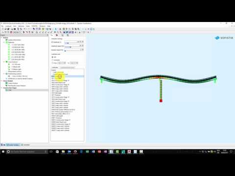
After that change we add the LC 2 with additional loads to the stage sequence in tab “Loads” and run the task. After the analysis finished, you should check the results with:
Report: Check the printout
Result: Check stresses inside cross sections for differnet load cases
GRAPHIC: Display and check the stress distribution of stress points along the bridge length
Traffic Loads
Please follow the explanations of chapter Traffic Loads from the General Workflow description.
Combinations
Please follow the explanations of chapter Combinations and Superpositioning from the General Workflow description.
Design
Please follow the explanations of chapter Design Checks from the General Workflow description.
Documentation
For the final documentation, you can collect all single reports and generate a complete document. Please follow the explanations of chapter Generate Report from the General Workflow description.


