Storey Checks - GUI#
Interactive SSD task to perform several storey checks, e.g., Weak Check or Second Order Check. Checks may rely entirely upon geometry or also load situations. Results will be available as tables and figures. Because calculation happens on the fly, they can be examined immediately within the task. To create the report, execute the task as usual.
See also
For more information about the individual checks, e.g., formulas, default or target values for the calculations of this task, see the following page Storey Checks - Theoretical Principles.
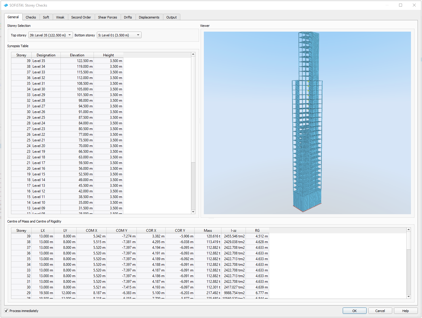
GUI Task Storey Checks - General Tab upon start (click on image to enlarge)#
General#
Provides storey level information for the project, taken from the database of the project.
Storey Selection#
Define the elevation range to be considered for the storey checks by selecting the top and bottom levels in your project. This selection does not affect the Synopsis, Centre of Mass and Centre of Rigidity tables.
Storey Synopsis, Centre of Rigidity and Centre of Mass#
Storey Synopsis gives a tabular overview of the general storey level definitions, e.g., elevation and height, with Centre of Rigidity (COR) and Centre of Mass (COM) in a separate table below.
Interactive Viewer#
A 3D-view of the model to quick check your geometry is available in Interactive Viewer. To highlight specific storeys, click and drag in the synopsis table to the left.
Note
The highlighting does not affect the storey checks.
GUI Task Storey Checks - General Tab - Storey Highlighting (click on image to enlarge)#
Hint
To change storey level information, go to your pre-processing tool, e.g., ![]() SOFiSTiK Analysis + Design or
SOFiSTiK Analysis + Design or ![]() SOFiPLUS(-X).
SOFiPLUS(-X).
Checks#
On this tab, all other necessary settings for the storey checks are made. Choose among the supported design codes, define thresholds and other values for the checks and select the relevant load cases.
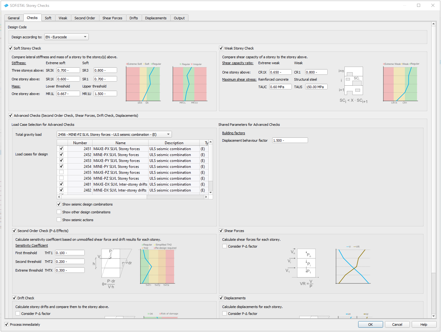
GUI Task Storey Checks - Checks Tab (click on image to enlarge)#
Note
The following restrictions apply:
Thresholds |
do not influence the outcome of the calculation but merely represent values the calculation results are checked against. |
Other parameters |
are being used for the calculations and influence their outcome. |
Design code#
The following two design codes are supported:
EN, acc. Eurocode 1998-1:2004 [1]
US, acc. ASCE/SEI 7-16 [2]
The design code selection has direct influence on the formulas used for the load dependent checks, and on the default values for the following parameters:
Parameter |
Description |
EN |
US |
|---|---|---|---|
QD |
Displacement behaviour factor
 (EN), (EN),Deflection amplification factor
 (US) (US) |
1.500 [-]
-
|
-
1.500 [-]
|
IMP |
Importance factor |
1.000 [-] |
1.250 [-] |
Parameter |
Description |
EN |
US |
|---|---|---|---|
THT1 |
First threshold |
0.100 [-] |
0.100 [-] |
THT2 |
Second threshold |
0.200 [-] |
0.250 [-] |
THTX |
Extreme threshold |
0.300 [-] |
0.250 [-] |
Parameter |
Description |
EN |
US |
|---|---|---|---|
D2HX |
Allowable threshold for the drift ratio |
0.0075 [-] |
0.0150 [-] |
NRED |
Reduction factor |
0.500 [-] |
1.000 [-] |
POI |
Point of interest for determining the drifts |
COM - Center of mass |
MAX - Maximum drifts |
Hint
Because the choice of design code affects the available inputs and the default values, the task will be reinitialised and values can be lost. For more info about the influence of the design code, see Storey Checks - Theoretical Principles.
Regularity Checks#
Soft Check and Weak Check are solely geometrical and activated by default. Reasonable thresholds are suggested but can be modified.


Hint
Click on images to enlarge, click link on image caption to be taken to the corresponding section of Storey Checks - Theoretical Principles.
Advanced Checks#
Second Order Check, Shear Forces, Drift Check and Displacements are load-case-dependent, and therefore deactivated by default. If desired, please activate the group box and control the load case pre-selection.
By default, load cases are filtered for design load cases of type Earthquake and the relevant load cases containing storey results are pre-selected. If needed, the filters can be amended and other load cases can be added to the checks.
 |
 |
 |
 |
Hint
Click on images to enlarge, click link on image caption to be taken to the corresponding section of Storey Checks - Theoretical Principles.
Soft, Weak, Second Order, Shear Forces, Drift, Displacements#
The results tabs of the graphical user interface are similar for all checks, with result tables on the left and interactive plots on the right side of the screen.
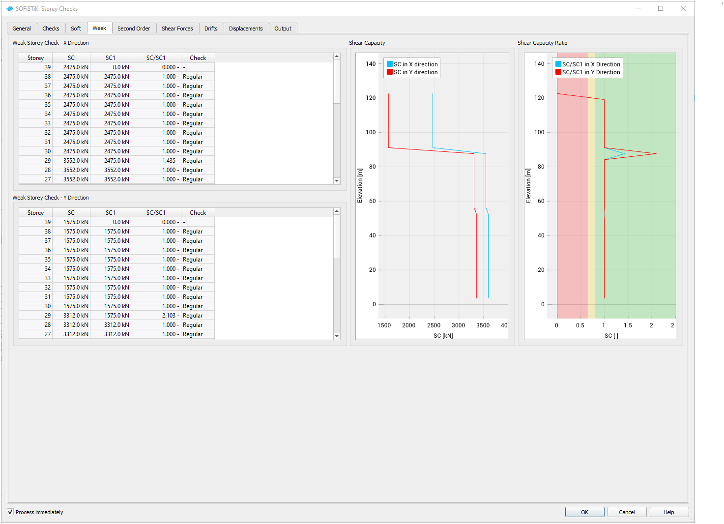
GUI Task Storey Checks - Weak Storey Check Tab#
Noteworthy behaviour of the elements:
Result tables on the left side of the screen
Tables are sorted in a top-down approach by default to match the building and the plots. They can be rearranged with a click on a the column header, e.g., to sort it according to the outcome of the check.
Result plots on the right side of the screen
Plots show the results over the height of the building (elevation on Y-axis) and the respective result on the X-axis. All graphs within one plot share the same result type.
To highlight an individual result, hover over its entry in the plot legend.
To hide or show individual results, (de-)select them in the plot legend.
Use the mousewheel to zoom in and out. If you position the cursor on an axis, the zoom is unilateral. Click and drag on the plot area to shift the graph.
Hint
The result tables and plots are read-only and the GUI always displays the decisive load cases only. As such, any changes, e.g., filters and sorting, have no influence on the printout. See Output for more information.
Output#
This tab controls the printout of this task. By default, all plots are enabled and the text output is kept brief. It is possible to set the output individually for each check or uniformly for them all.
On the left hand side, the tabular output can be adjusted.
The buttons at the top adjust all checks equally. To control the printout of individual check tables, use the combo boxes. The extent of the output for each check is listed in the respective rows. Options usually entail decisive load cases only or all load cases.
On the right hand side, the graphic plots can be enabled/disabled.
The buttons at the top adjust all checks equally. To disable/enable the printout of individual check plots, use the combo boxes.
Hint
Only selected checks can be displayed in the printout. A synopsis table at the beginning of the report allows for easy verification of the settings.